She flew!

The last engine run was in October 2021. Since then we’ve been waiting for paperwork to go between IAA and ILAS. This finally got sorted out the first week of January and on 15th January 2022, 5 years after her ground-loop in Florida on 10th December 2017, N4180V took to the skies as EI-AEN.

Steering was aided by tail-feathers from N3832V which last used them on 23rd Feb 2002.

There is still work to do – her rigging is not yet perfect so she has a heavy wing; but the project is very near completion.

First Engine Run

Just what it says on the tin. After much work including replacement of all plugs and the second complete set of fuel lines we fueled her up with 20L of 100LL Avgas and fired up the engine.

There was no drama, a couple of minor weeping leaks from the fuel system so on the day all went well.

That is, of course, to skip neatly over the trouble we had getting the oil pump to prime. Ended up having to remove the starter, alternator, magnetos and accessory case to make sure the oil pump worked at all. We manually primed it and turned it over and oil happily spouted from the appropriate orifice. Checked the accessory case gasket – it was correct, and put it all back together … did I ever mention how much I love doing safety wiring, especially doing it over?

Reinstalled the various items, timed the magnetos and filled up with more oil than should have been necessary. I recharged the battery and turned the engine on the starter with the mags off until oil pressure showed on the gauges. Since then all has been fine on the oil pressure front.

Wings and vinyl

Putting the wings on was a drama! So much so, that there are no photos. It took 4 of us about 5 hours to get 10 bolts installed with much bleeding and aggravation.

After the wing war was won it was on to the vinyl. The only reason for changing from the original design was the registration needs to be ICAO compliant. The plan is to fly to the UK and eventually to France, so undersized reg letters might have been OK, but won’t do for international travel.

To make space for the letters I decided to extend the red stripe up the side as in the photo. Eventually a matching pin-stripe will go around the red to blend into the original design a bit better. The tail logo is much bigger than original, but as the reg is not going on the tail, it seemed sensible to make the logo more visible.

The metal ID plate is last piece of ID work to meet the registration requirement.

The move to Kilrush

Catching up on a few milestones that have come and gone over the past year.

End of April 2021, EI-AEN moved to Kilrush airfield in Kildare. The shortage of hangar availability generally pushed me into making the move sooner than I intended. As it turned out this was about 3 months too early, as there were plenty of tasks that could have been completed in the workshop, which took a lot longer to complete at the airfield.

On the day, all went well and the aircraft ended up tucked into a nice corner of the hangar next to the door. There is now 1 hangar-mate, a Bonanza, that I need to move (carefully) outside when taking EN out, but no one needs to move EN to get their aircraft out.

The Rudder Situation

One of the interesting things about working on an old aircraft rather than building a kit (which was my other choice) is the archaeology! Figuring out why someone did what they did when fixing, installing or changing something has been interesting. In a few cases the question was more along the lines of “how did they get away with that?”!

The reason N4180V was sold was she ground looped into a runway sign and minced the H-stab and one side of the elevator. The gentleman in Humble, TX from whom I bought her had already sourced a H-stab and fin from another aircraft which itself had been crash landed on a railway embankment. When I test fit the rudder onto the “new” fin it didn’t work out all that well. “Right Rudder, Right Rudder!” is all well and good, sometimes you have to go left.

It appears that the rudder was (at least partially) rebuilt at some point. It may have been quite early in her life as it is not covered in the logs that I have. The top of the rudder, the red part, was when attached was not square. The of course raised the question of how did it fit on the plane?

My best guess is that when they finished on the rudder and went to fit it this happened (below) and rather than do the rudder again keeping everything square, it was easier to shave the top of the fin to create the clearance. I was not willing to do this. I had a buddy check his rudder (which also happened to be off the aircraft) and it was near perfectly square, so I decided to rebuild the top of the rudder.

The first step was seeing if the existing rudder could be “fettled” into place, which it could, but I didn’t like the look of the holes in the skin and the underlying rib. It looks like it had been re-riveted once before using all pop-rivets and the holes in the rib, just didn’t look great. Nothing for it but to replace the skins!

Using lots of Clecos and clamps and remeasuring multiple times the new skins went on square and the resulting rudder fit the “stock” fin. The hole pattern was moved to fall half way between the old holes in the rib. The rib itself was not rebuilt, in fact was never removed from the attachment point to the corrugated skins.

As always my corrosion paranoia kicked in and everything got a coat of etching primer on the inside.

Solid rivets were used along the bottom except at the end where there was zero clearance for the bucking bar. The leading edge was fitted using pop-rivets (4mm) with a large head to reinforce and cover the holes as of course the original positions had to be used, albeit with new holes in a fresh skin underneath.

Painting occurred – the less said about my painting the better.

Filler was involved in a few locations, especially at the nose of the rib! The lump of lead inside that balances the rudder was pinned in place as originally installed and then pop-riveted along with the skins.

The fin and horizontal stabilizer are installed, shimmed and measured. Cables and pulleys are in place and the rudder and elevators will be hung as soon as the bolts show up from the supplier!

Quickie: The panel clock

One of the instruments that is staying in the panel is the clock. It is a wind-up 8-day clock that I think is original to the aircraft. The red hands allow you to set your waypoint ETA and then watch the white timing hands catch up by which time hopefully something looks recognizable. No it doesn’t have a magenta line!

It’s a Wakmann which it turns out is a US company, originally from Portugal, that imported Swiss watch and clock components. They completed final assembly in the US, thus avoiding the protectionist duties applied to imported finished products to protect domestic US producers.

Monochrome Watches tells the story.

It’s back in place now, next to some slightly moe recent tech!

Electrical System Finished (mostly)

I gave up onĀ  logging hours. As I don’t have a 51% requirement, it’s a renovation not a kit build, there is no regulatory need to show amateur effort percentage. Of course, other than the engine rebuild, it’s 100% my effort anyway.

Panel completed

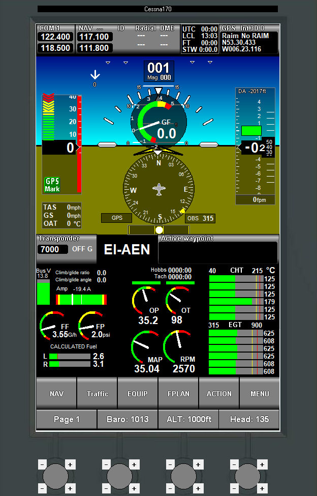
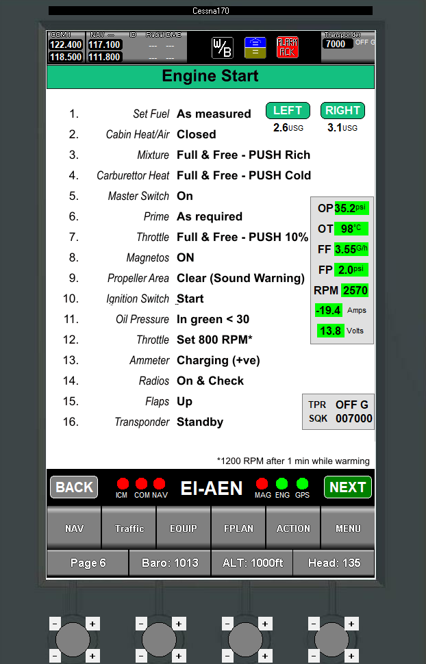
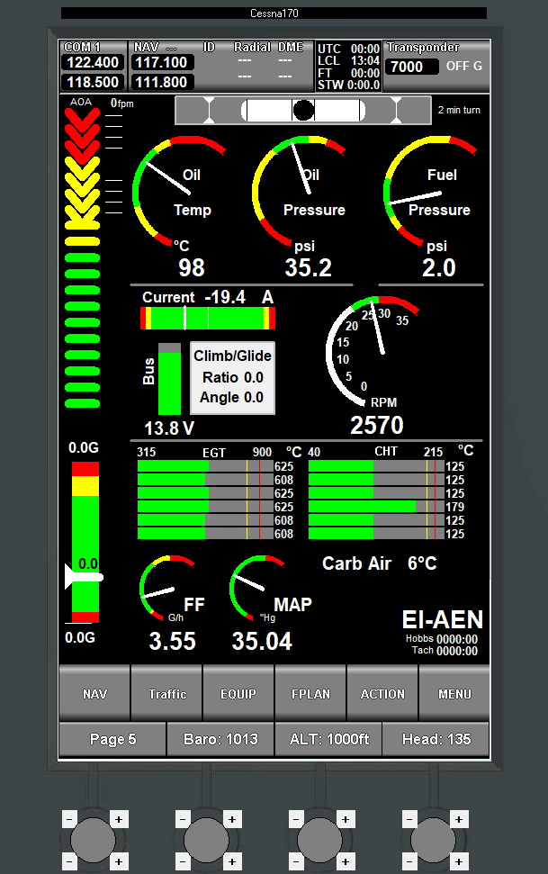
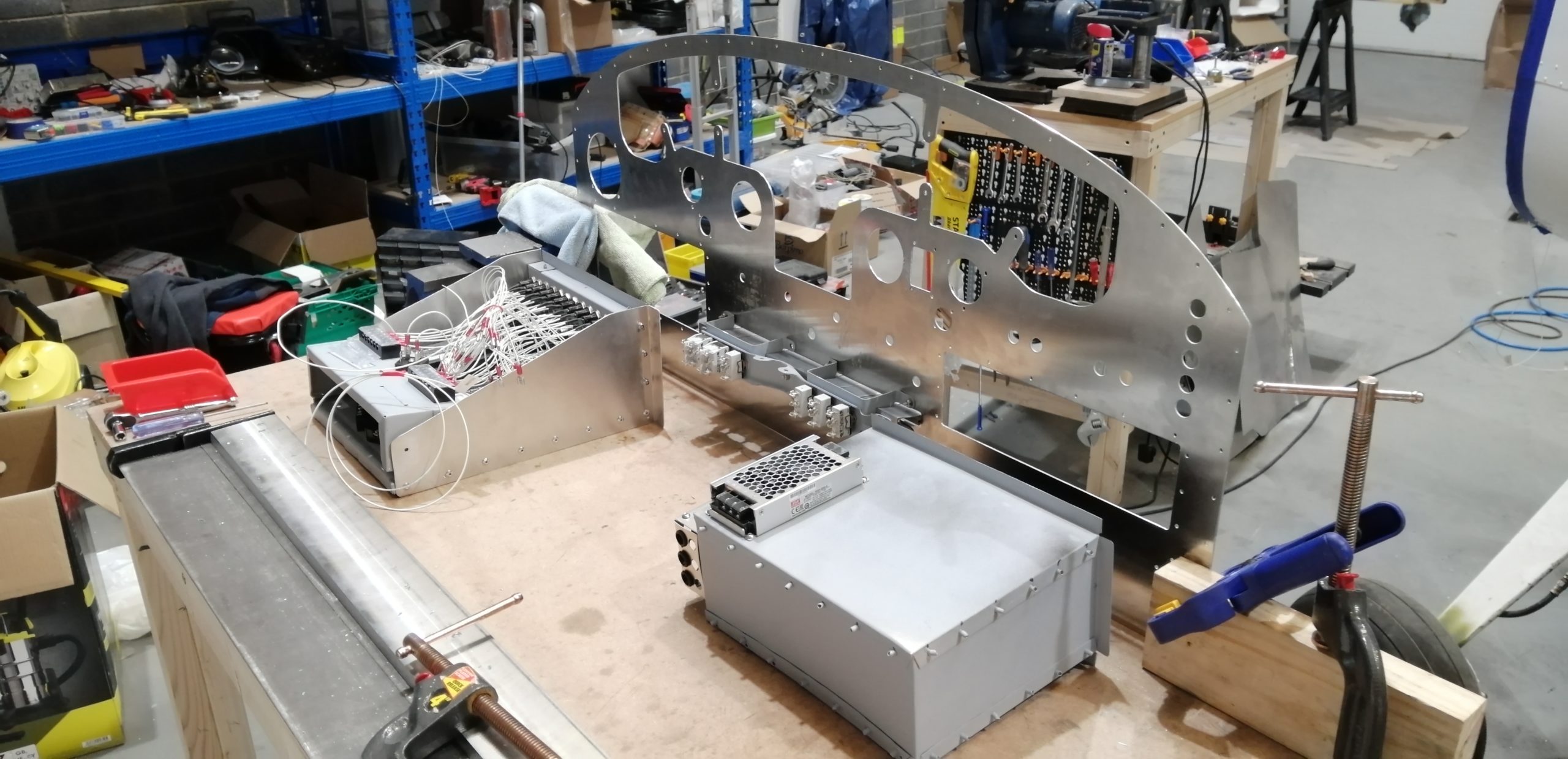
The panel is ready for installation. All its bits and pieces are installed, the instrument harness and pitot static tubing are all connected up.

Electrical system wired up to switches

The electrical system is based on a Bob Nuckolls design. Unlike the traditional Cessna master and avionics-master, it had two separate buses with no single point of failure. This is achieved by having a separately switched cross-feed from the battery to the “Essential Bus” and the traditional contactor-driven master switch sends power to the “Main Bus”. There is a feed from the main to the essential bus through a diode that prevents back feed from the eBus to the main bus.

All that sounds more complicated than it really is. In practice the critical (or essential) systems run off the eBus and everything else off the main bus. In the event of an alternator failure you switch off the master: that’s it. This leaves only the cross-feed connected to the battery, thus all your heavy loads are off and the critical stuff is on. The endurance on eBus only with an Odyssey PC680 is over 4 hours which is similar to the fuel endurance of the aircraft.

The idea here is instead of dead alternator = land immediately (pan pan, I have 20 mins to dead battery) it becomes: continue to destination / appropriate airfield, switch on the master when on approach and land as normal. To achieve this endurance every incandescent bulb has been replaced with LEDs and the only real current hog is the pitot heater.

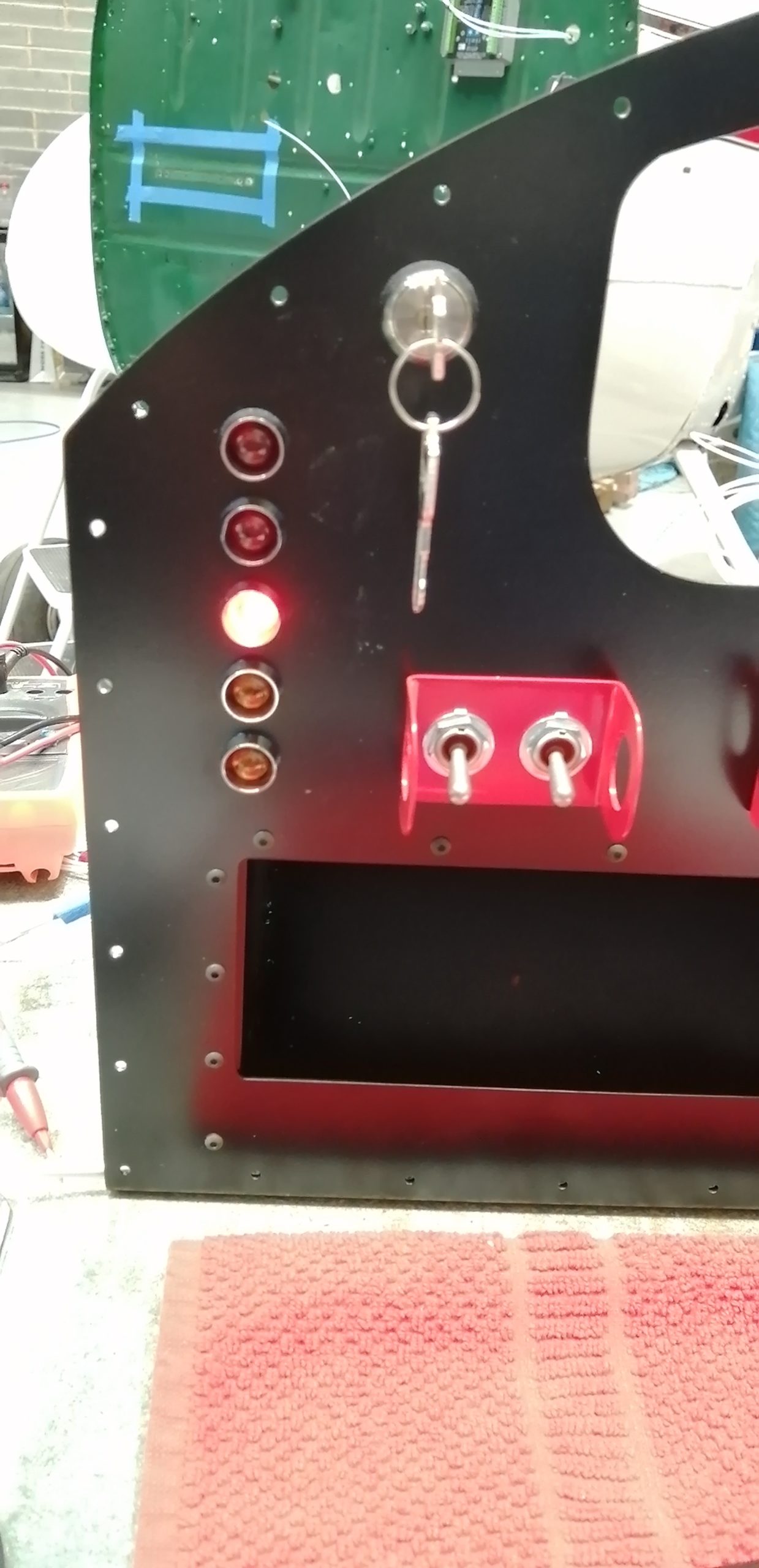
Annunciator wired and tested

How then do I know the alternator bit the dirt? What if the cross-feed isn’t turned on?

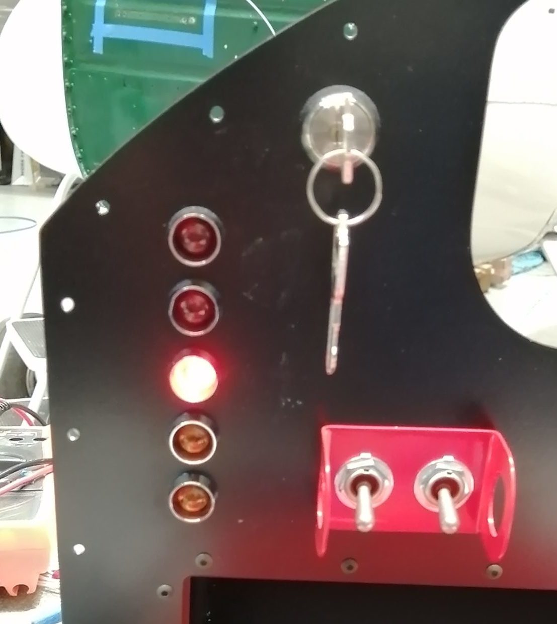
Annunciator – in need of labels.

It started out in the schematic drawings as a couple of warning lights and ended up with these five. It was fairly straightforward until I realized that three of them are activated by a +ve signal and the other two -ve. That means the three have no voltage until the switch is on, the other two have voltage always but should only be lit when the ground connection is made by the failed device.

The warnings and cautions are like this:

  • Alternator OFF (Red)
  • Pitot Heat FAIL (Red)
  • eBus Feed OFF (Red)
  • Starter ON (Amber)
  • Fuel Pump ON (Amber)

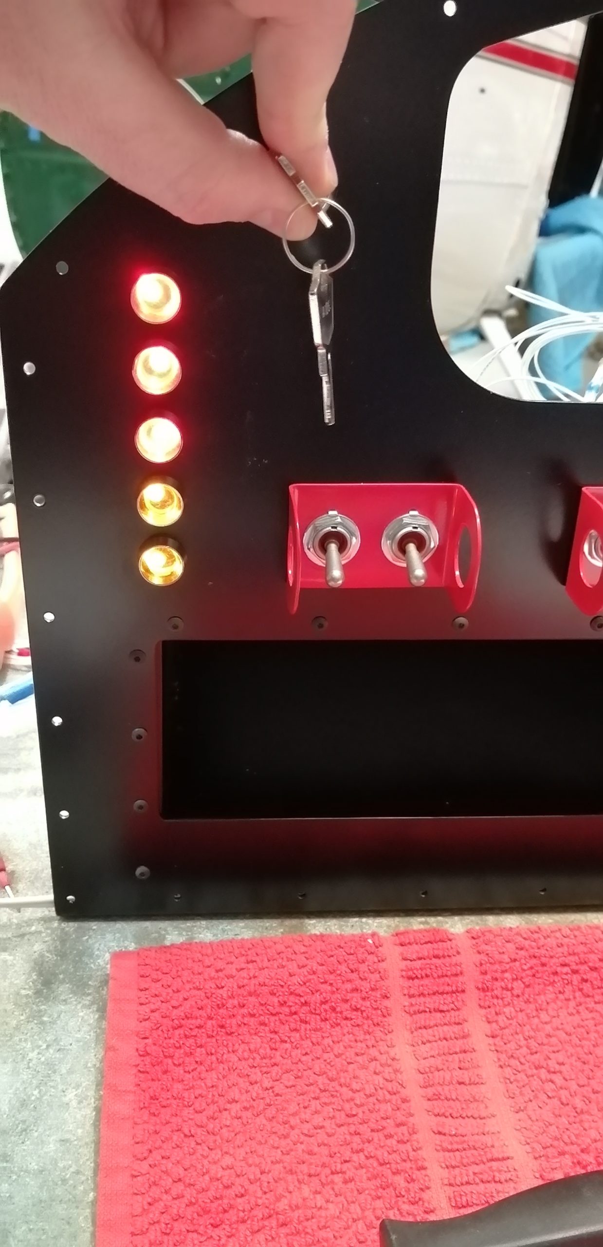
Once all that was wired up (on paper) I came to the conclusion that I need to be able to check that the lamp itself is working during preflight. While they are LEDs and should last nearly indefinitely the circuit might fail somewhere, better to know. I also needed a push-button for start as I’m not using the Off-Left-Right-Both-Start key switch; mostly because the one that was in it is in rough shape and I’m too cheap to buy a new one. The key-switch I used from a reputable UK manufacturer is intended as an industrial panel lock out switch and was 20% of the price of the aviation one. The mags are on a pair of toggle switches just because. It has three positions – centre is off, left momentary (springs back to the middle) is for test and right momentary powers the starter contactor.

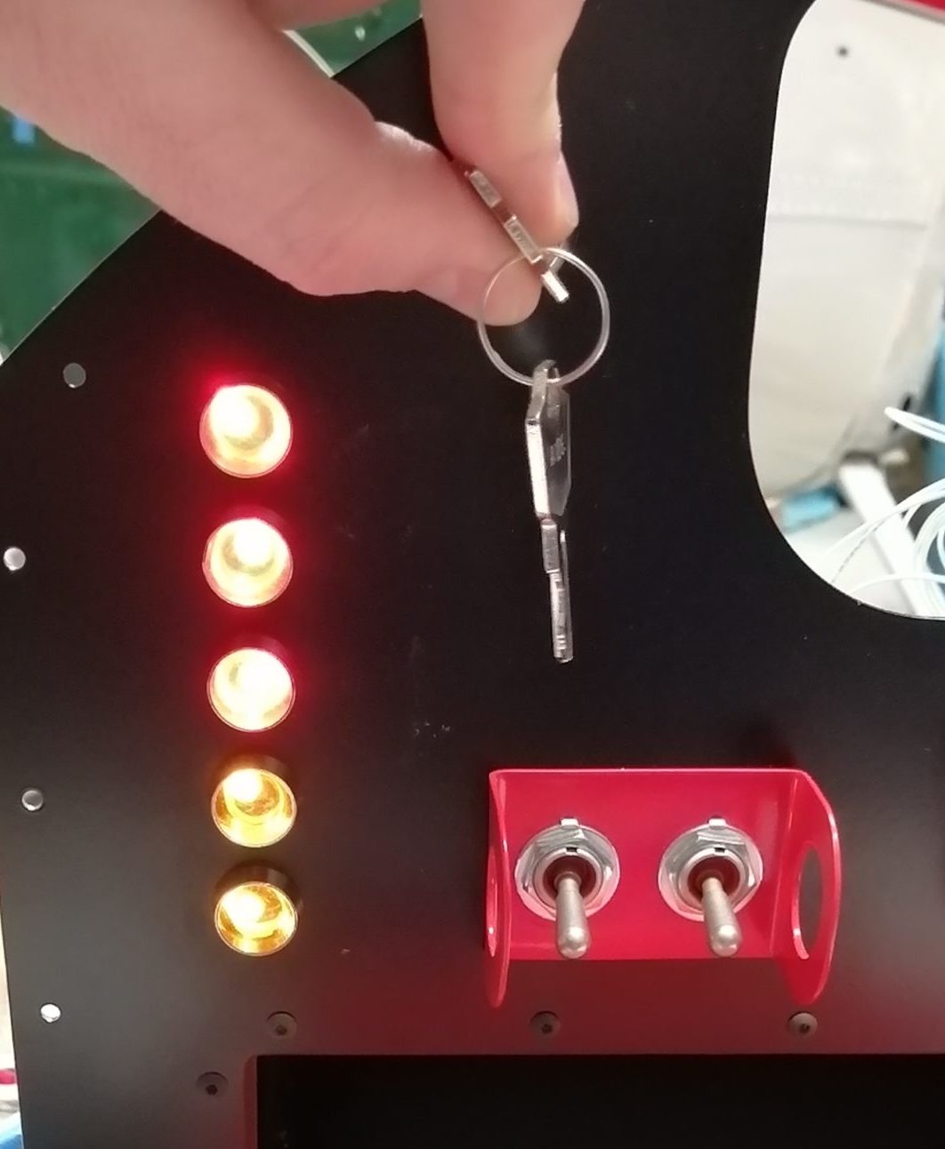
In the test position all the LEDs are powered to make sure they are still alive!

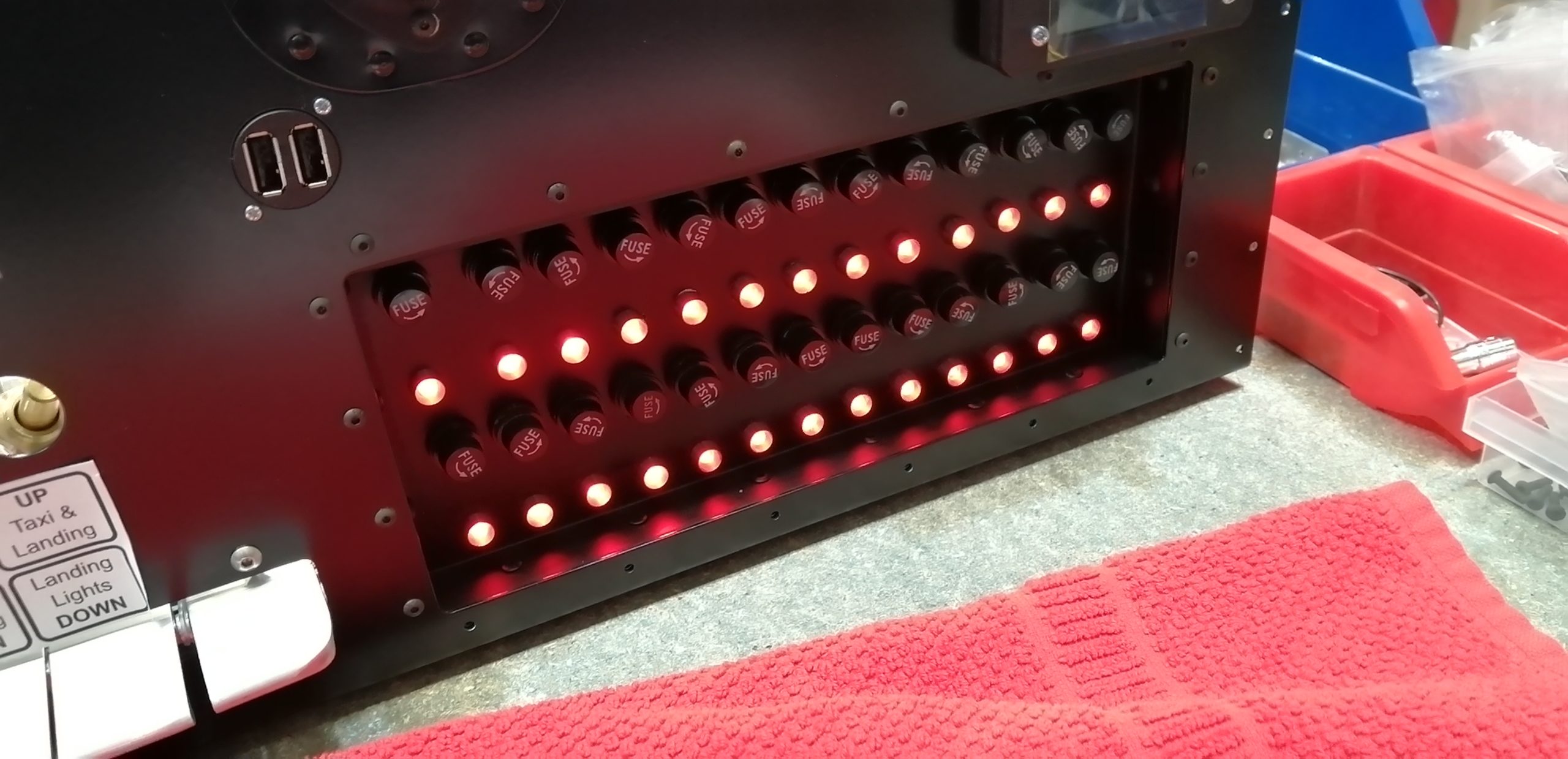
The test position lights the lamps and grounds all the test LEDs on the fuse panel showing if any of the fuses are dead.

So far so good. The problem I discovered as I was wiring it up was that when I powered up the test circuit to make all the annunciator LEDs come on it would then connect power to the +ve signal devices so the fuel pump, starter contactor and eBus would get power via the 22gauge test circuit: not the plan.

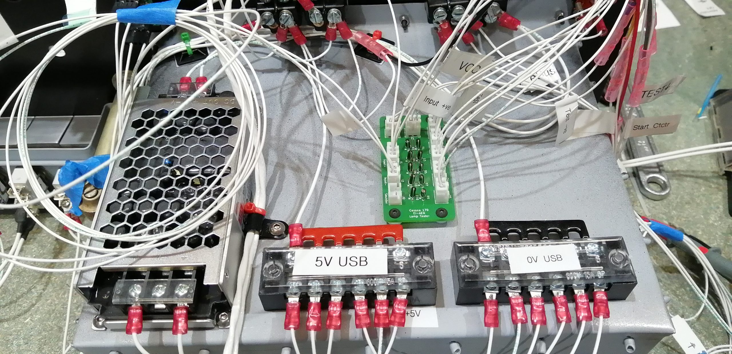
The result was a set of diodes. I found a couple of circuit diagrams of “common cathode” and “common anode” lamp test modules online which it turns out equate to the +ve and -ve signals mentioned about above. I used KiCAD (open source electronic CAD package) to magic up a PCB and uploaded it to aisler.net and along came the solution.

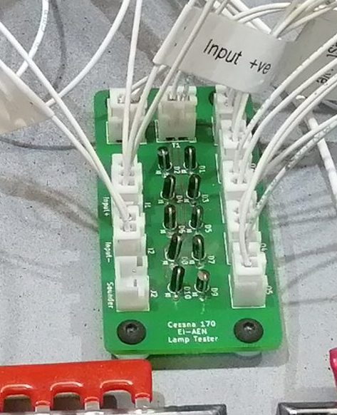
Annunciator lamp test module

This allows the key switched lamp test to work and made wiring up the annunciator lights, signals etc. much easier.

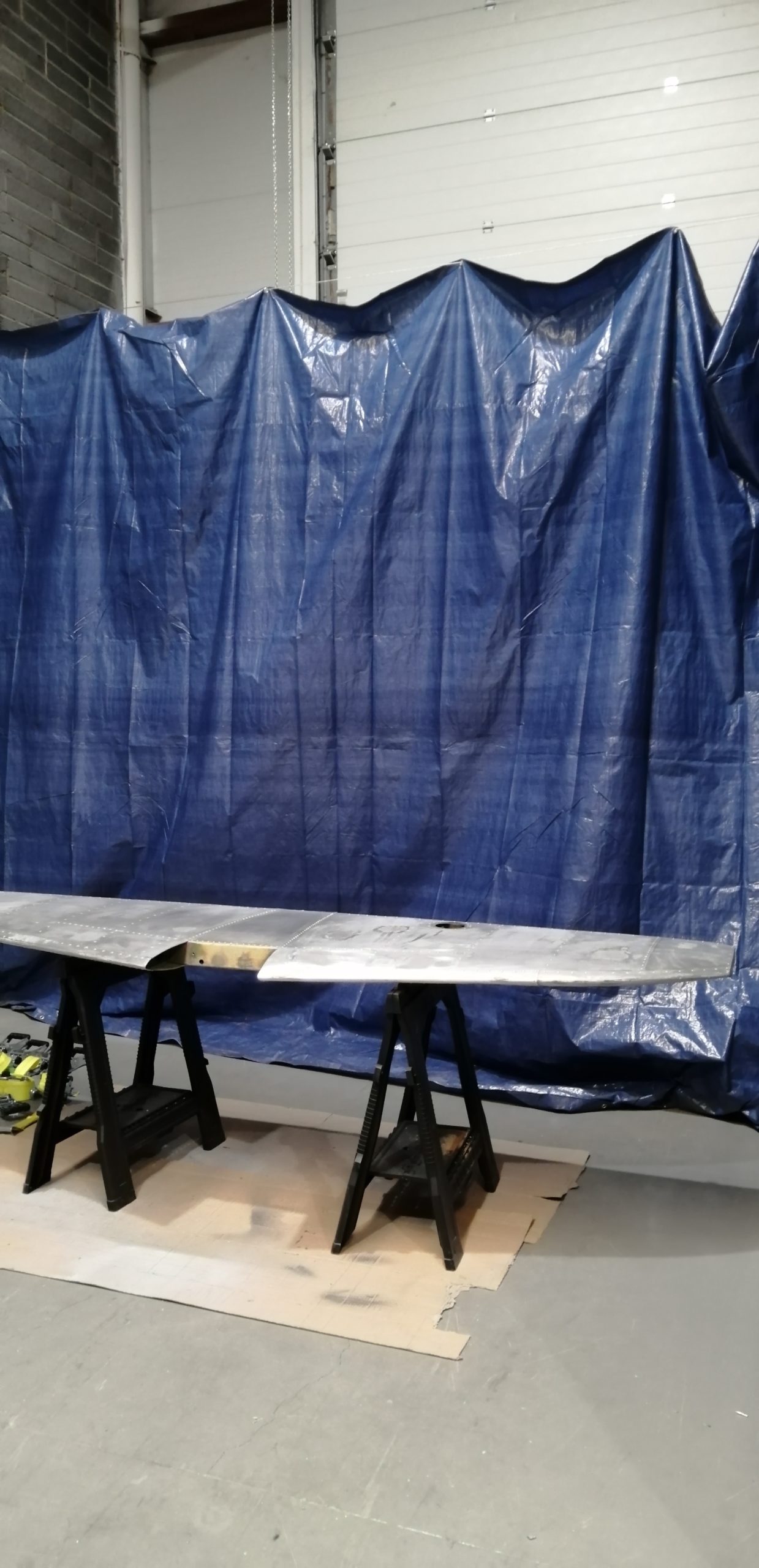
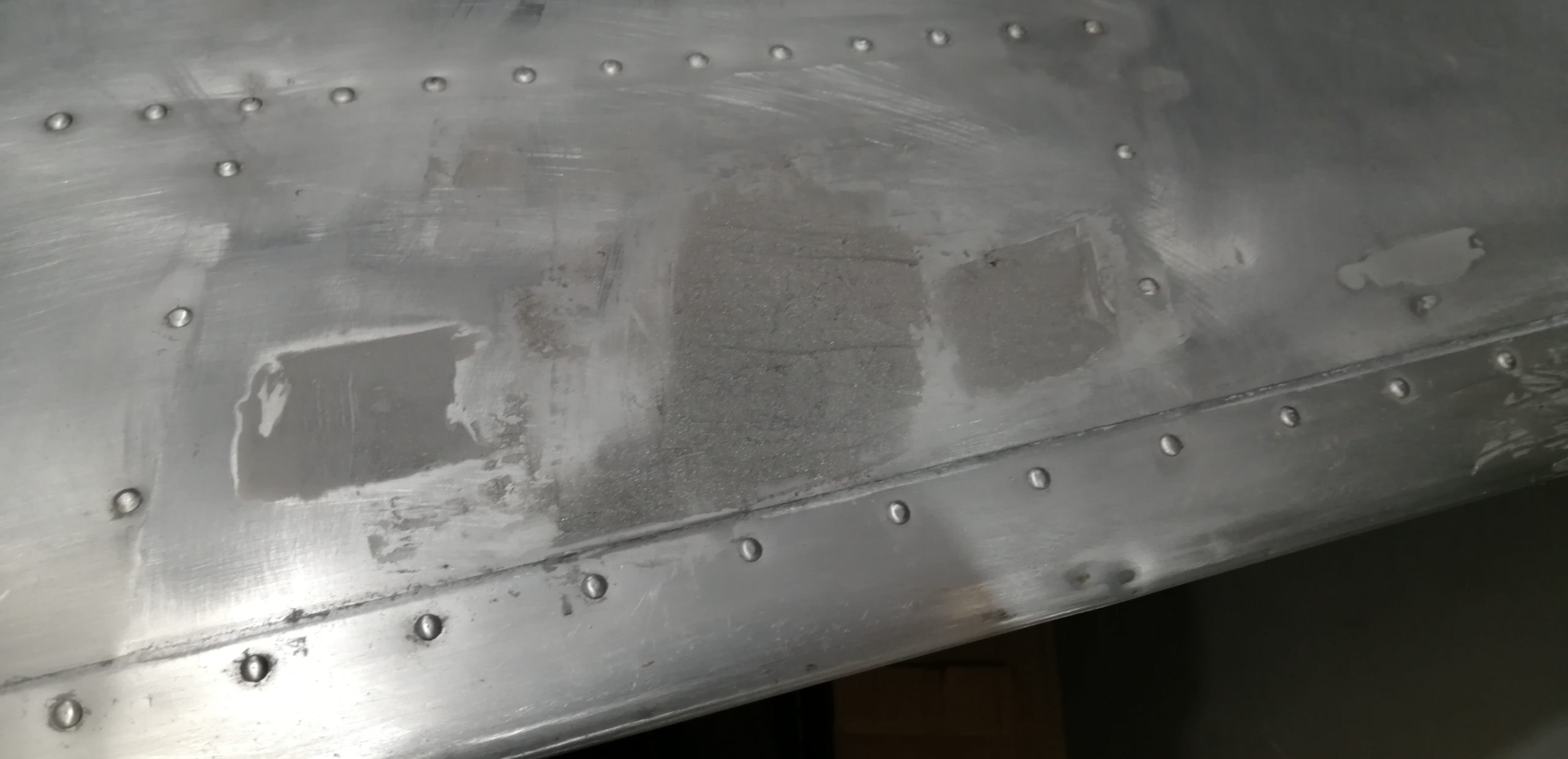
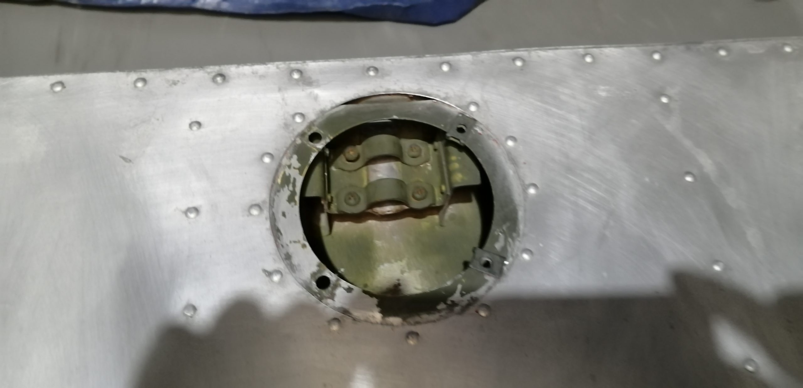
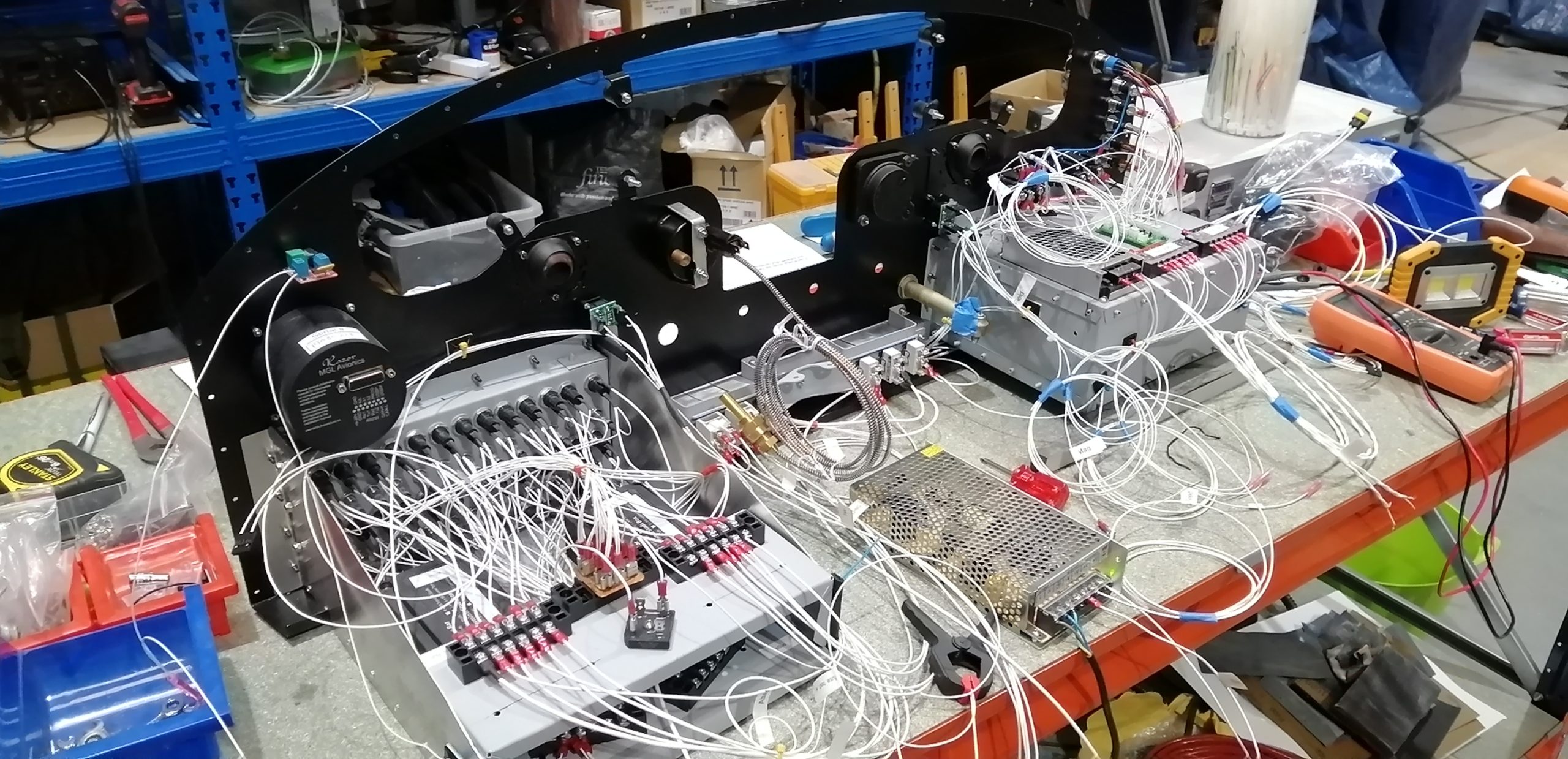
Wired for pitot heat

With the addition of 12AWG aircraft wire the supply to the main bus and the wiring for pitot heat is in. I put an IP67 rated automotive disconnect at the wing root as with everything else that routes into the wings. That should make the wing installation literally plug and play.

USB Charging

With everyone using tablets and phones in flight these days there is always a need to plug them in. There will be no smoking, so no need for the cigar lighter socket with a converter jammed in and wires all over. I was unwilling to use the expensive certified charging sockets, especially as I wanted 5 charging points. The result is a “transport category” isolated DC-DC converter that turns 12V into 5V which in turn is fed to simple USB sockets.

This is all run through a single piano key, so the whole USB charging system can be shut off.
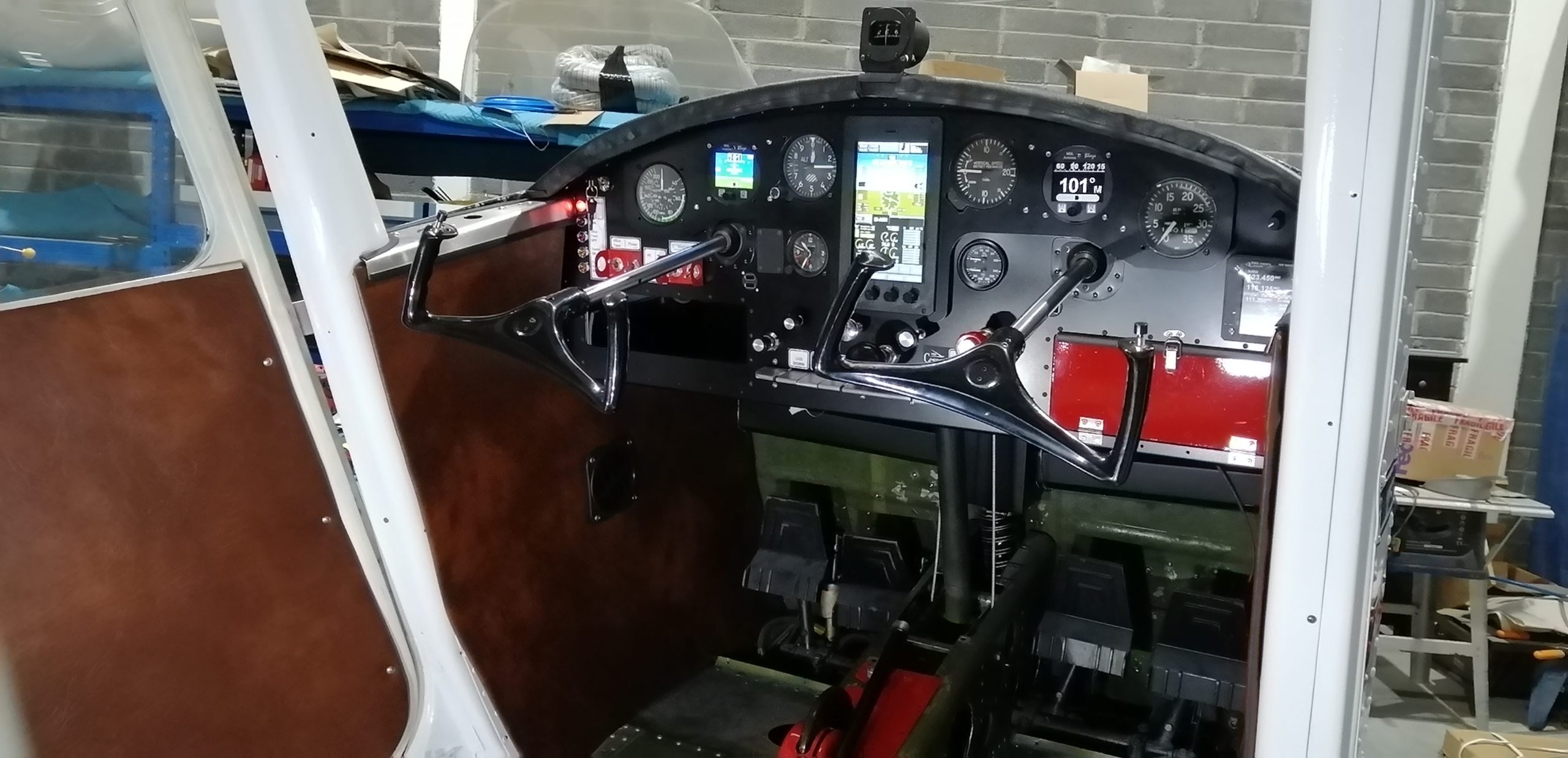
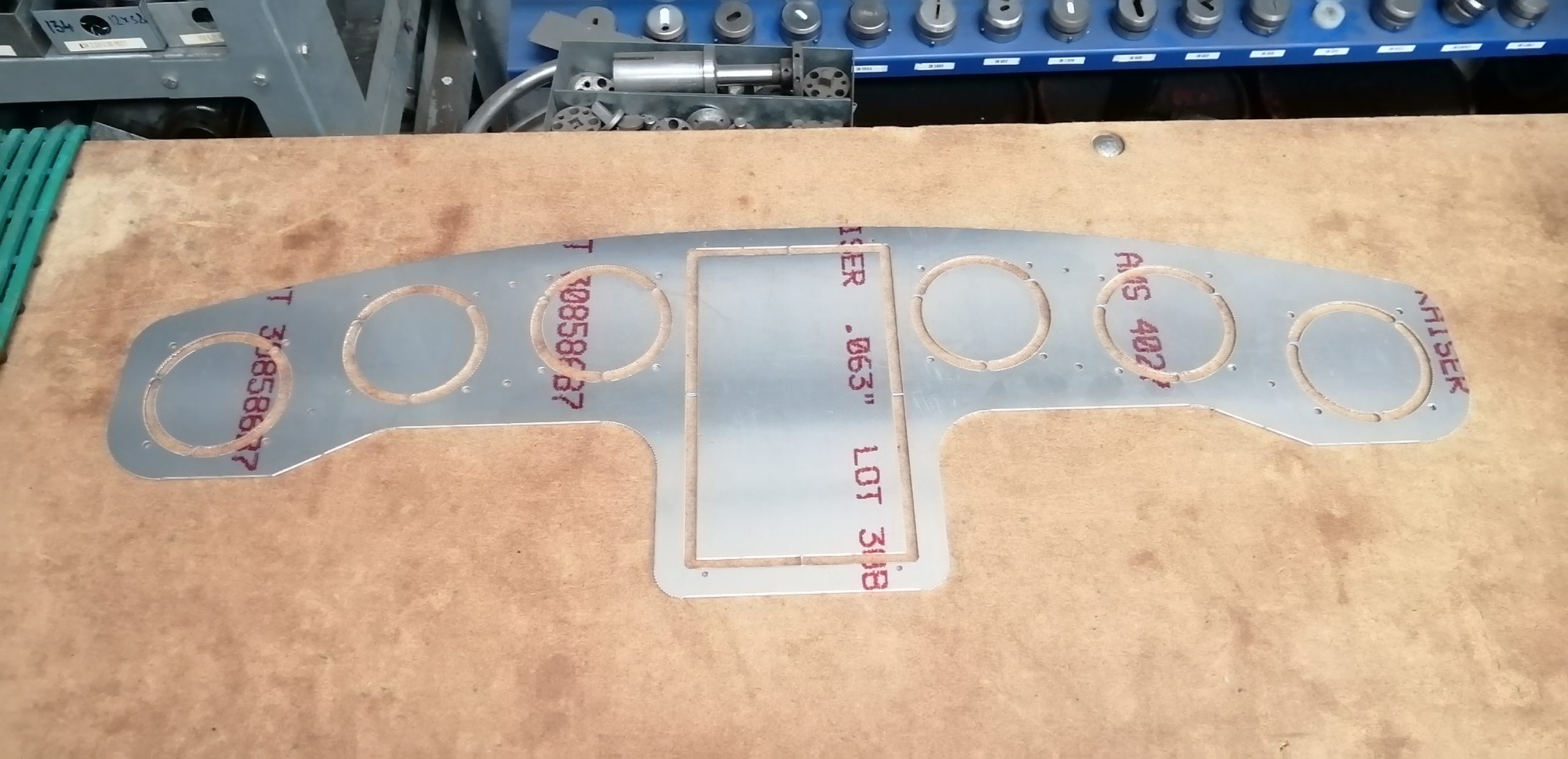
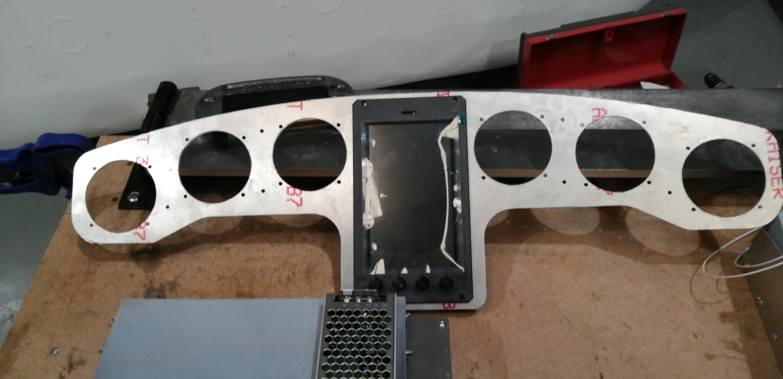
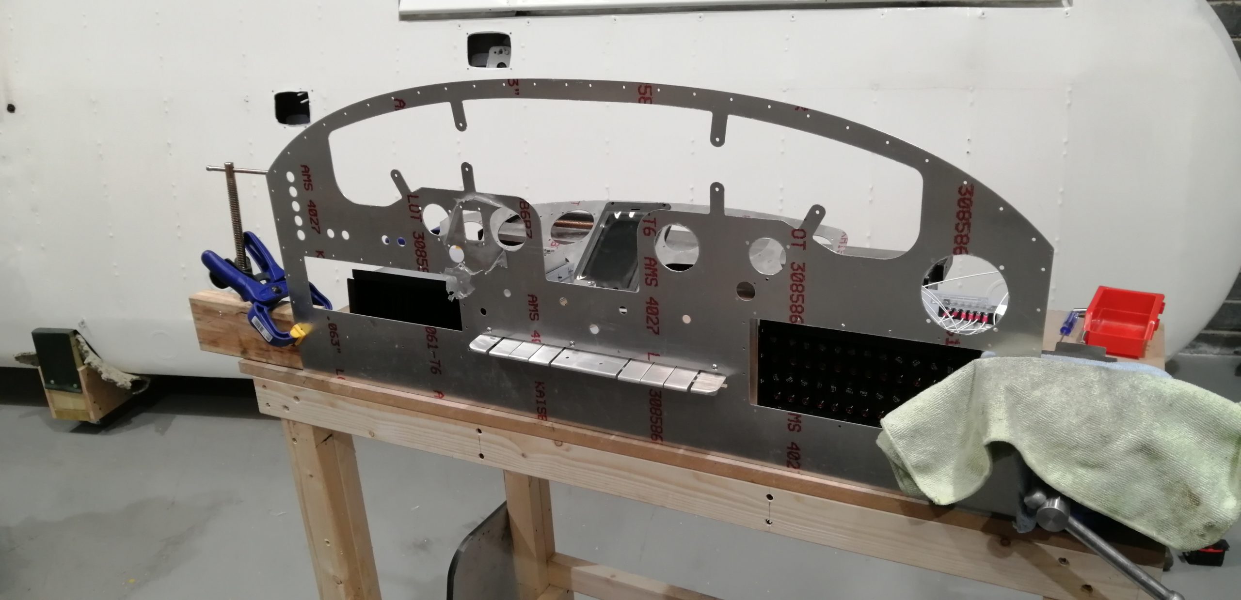
Ready to install

The picture shows why I gave up logging hours. The panel is relatively simple from the front despite its capabilities. I wanted it to look sort of period, the purists will of course object to any kind of glass, while having the capabilities and safety of modern avionics especially solid state AHRS. The complexity is all behind the scenes.

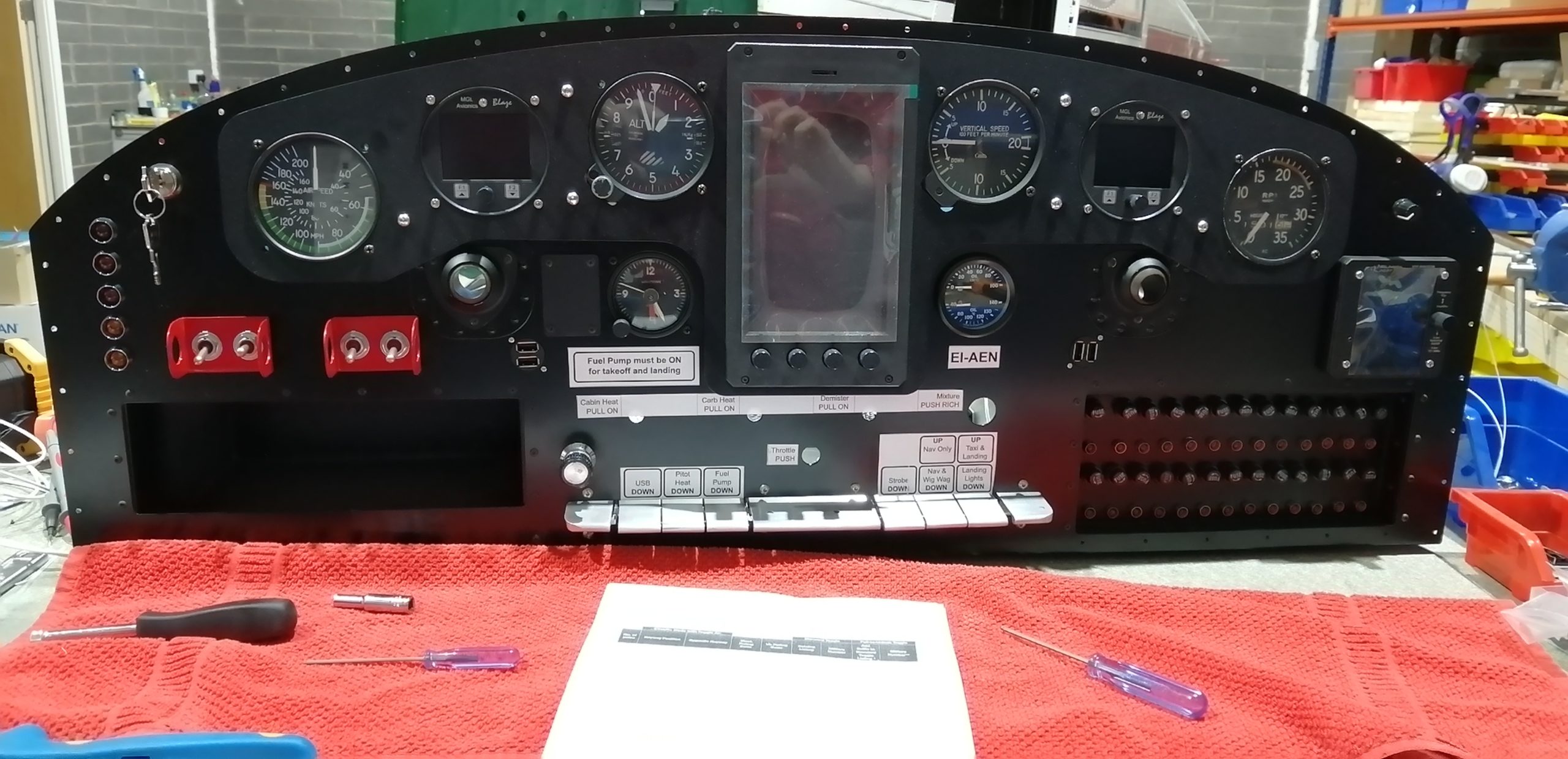
The panel is now tested and almost ready to go into the aircraft. I intend to add a door on the fuse panel to look a bit like the glovebox on the original. Once the new heating ducts are bolted in I will install and connect up the panel.

Panel Progress

The CAD file has finally been applied to metal. 6061-T6 Al .0625in thick.

The work was done at Watermark Engineering in Dublin; the owner is an avgeek who is plans-building a Fiesler Stork replica. Using their punch press we (the operator with looking on) punched out the panel and the shock-mount instrument sub-panel.

First up was the shock mount which has the multi-function display in the middle. I’m trying to keep the spirit of the original panel while adding the safety of engine monitoring and electronic AHRS. While I’m using it as an MFD, the unit (MGL iEFIS MX1) is actually a full EFIS with primary flight display, engine management and even an autopilot. The beauty of this unit is the level of configuration possible for the screens. I have designed several custom screens and started work on interactive checklists.

This is the stock Primary Flight Display Screen. It packs a lot onto a small screen and is not how I intend to use it. The checklists are able to show the relevant data directly on the list. The fuel level is manually entered at the start of the flight (as the tanks don’t have electronic sensors and I’m not opening the wings). The system then uses flow rate to calculate and display the remaining fuel in real-time.

The shock mount below is ready for paint.

From left to right will be: Airspeed, AHRS, Altimiter, EFIS, VSI, DI/AHRS (backup function), RPM (Tach). So if the 6-pack is supposed to be in front of the Pilot this is missing VSI, DI and Slip/Skid. However, the AHRS has the DI built in, so heading is shown on the DI. Thus all that’s missing is VSI and skip/skid.

The iEFIS let me build a screen that has all the engine management display, the VSI, slip-skid, AOA, and G-meter so rounding out and exceeding the 6-pack, while also allowing me to control the COM, NAV, and Transponder from the top bar of the screen.

All of that shock-mounts into the panel below which retains the piano keys and hides the fuse panel behind the glove-box door. The slot on the left is for my glasses and the (backup) paper chart I don’t tend to look at as I mount SkyDemon on an 8″ tablet on the yoke.

The punch press “nibbles” the shapes using various round and rectangular punch and die pairs. There was quite a bit of filing and sanding to do to finish it up. It certainly beat hand cutting it!

The result so far is shown below with the piano keys test fit.

If the panel looks too deep (tall), that’s because it is. There are two bends to be made along the bottom to reinforce by forming a u-channel along the whole bottom of the panel. The shock mounting points (tabs) need to be folded also. That’s beyond what I can do here, so it should be done some evening this week at Watermark.

From the back you can see the rebuilt piano key mount with new switches and the (seriously overbuilt) electrical system. Attached to the map box are a stratux (ADSB-in) and 5V power supply for 5 USB charging points to power cameras and tablets. Of course that’s about as tidy as it is ever going to look as the wiring will be a bit of a mess. Have to finish up the folding and painting before I get to that point.

Prepping – No not that kind!

I’m not a good painter. Which is why of course I decided to do it myself. However, I’m not really painting the aircraft, just patching and matching the donor tail. I installed some “curtains and I’ve ordered in some new LED flood lights, so at least I can see what I’m doing. I spent a lot of time cleaning up the H-stab which was reused from N3832V. There were quite a few dents and divots on the underside but nothing worrying. After lots of filling and sanding the parts are ready for Alodine and then paint.

Best news was finding the trim tab actuator that I thought was missing. It’s sad the things that #avgeeks get excited about; in my defence, they’re not really easy to find and very expensive!

Bending, Drilling, Cutting, and Filing

I’ve never so much as bent a piece of metal before this project so getting from zero to making panels, the new heating system and various doublers has been interesting. Since I got her I’ve been looking up at a raggedy hole in the roof of the cabin where the NAV antenna used to be attached. It doesn’t look like there was ever a backing plate and certainly not the doubler it should have to support it. I decided to patch the original hole, using AC 43.13, and relocate the antenna.

Unfortunately I didn’t save the before picture but here’s a few along the way:

Clecos are now my favorite tool! The patch has two pieces of .040″ 6061-T6, one sized to the hole and the other oversized to allow it to rivet around the hole.

The result is a flush patch. Not that I’m especially worried about drag optimization in a 48 rag wing, but if it’s worth doing … I’ll clean it up and give a lick of paint to tidy it up when I get to painting stuff in the next few weeks.

Next up was the new location for the antenna. I’ve put it just aft of the rear spar. This far back may add to “shadow” from the cabin, but I decided I liked the stronger position better. Also given the radio is in the back (controlled by the MFD) I’m able to run the coax up the inside of the control cable box, keeping it out of sight.

I put the COM antenna further back (at the last cabin frame) so it is adequately separated from the NAV antenna. Again, shadow may affect performance; if it does I’ll move it.

So, she now has a GPS puck, NAV, COM and ELT antennas all installed.

And shortly they’ll be hooked to the avionics rack.