My ILAS inspecter has stopped highlighting and emphaisising that it is critical to comply with AC-43.13 and do everything right. His new word seems to be “overkill”!
I probably went a bit mad with this, but I decided it was an opportunity to update the electrical system without being constrained by the certification system.
The existance of certified aircraft is a very good thing. It ensures that a member of the public can get into an aircraft and have a reasonable expectation that it is what it says on the tin. If I rent a C172 or a PA28, I can expect that it will behave as designed and hasn’t been hacked about. However, the unintended consequence of certification is how it has grown out of control as a self-sustaining bureaucratic exercise. The cost of certification is so ridiculously high that many advances in performance and safety have never made it into general aviation as the 1950s design “works OK and is certified”.
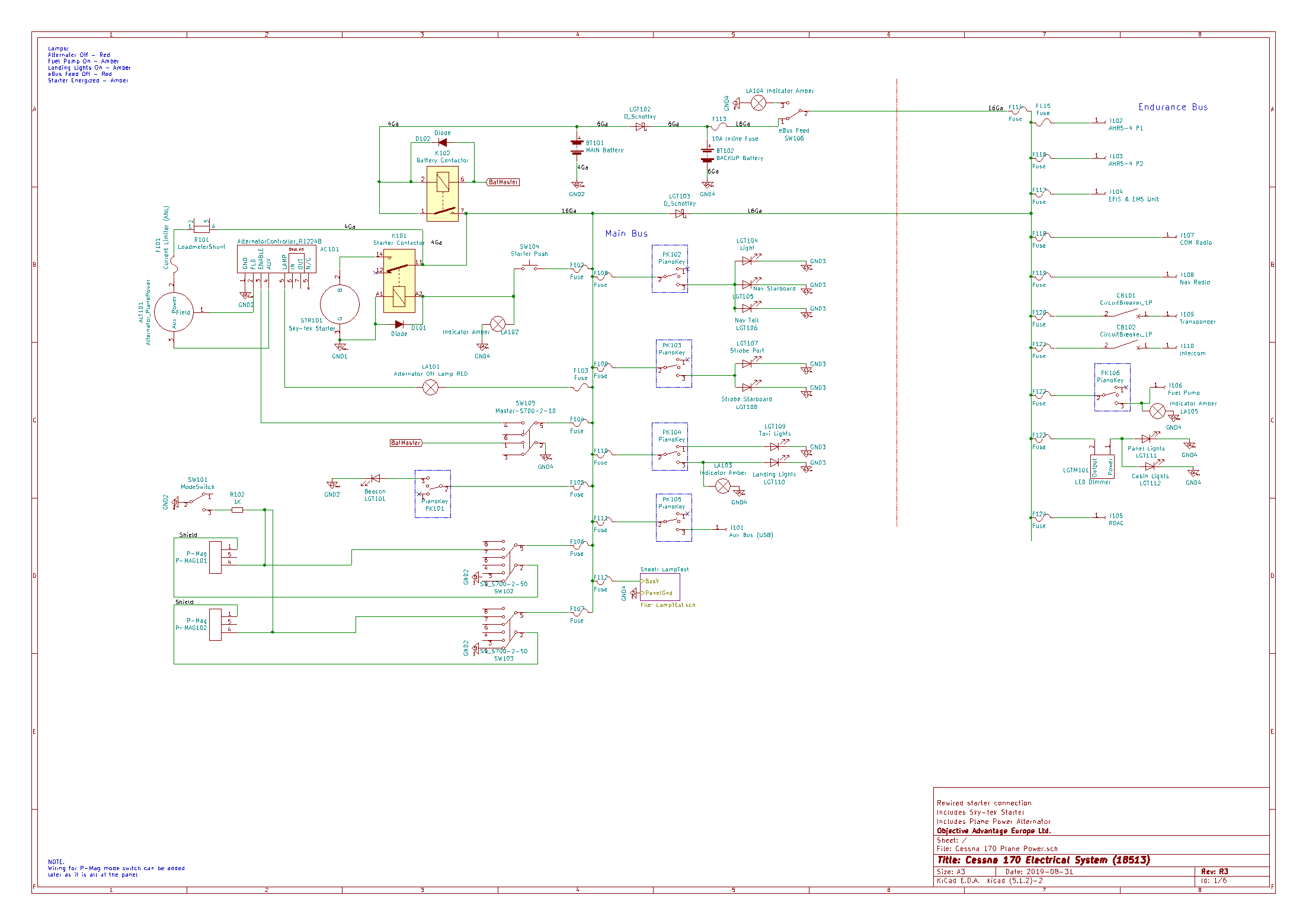
As a result things like electronic ignition systems are not used and single points of failure ilke the “avionics bus” persist. We’re still turning off electronic systems to protect against “spikes” which they are required to be able to withstand. This makes no sense when the EFIS or at least engine analyser must be on before startup in a glass aircraft. I enjoyed Bob Nuckolls’ book which may be purchased or downloaded from the AeroElectric Connection web site. I based my new system on one of Bob’s samples (in the back of the book) and modified it as required.
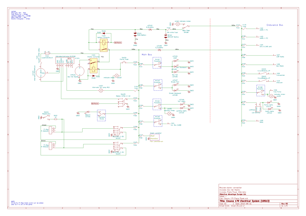
The result is a power system that has greater electrical endurance than the plane has fuel endurance.
- All bulbs now LED
- Strobe system (Whelan) removed and replaced by LED strobes
- 100% of wiring replaced. Except in the wings which I’m not recovering so can’t access the wires. They are not original having been replaced about 15 years ago when the wing was last recovered.
- Combination of main and backup battery can run the endurance bus for 4hours + in the event of alternator failure
- Backup battery in the cabin (back of the firewall can run the endurance bus for min 1 hour
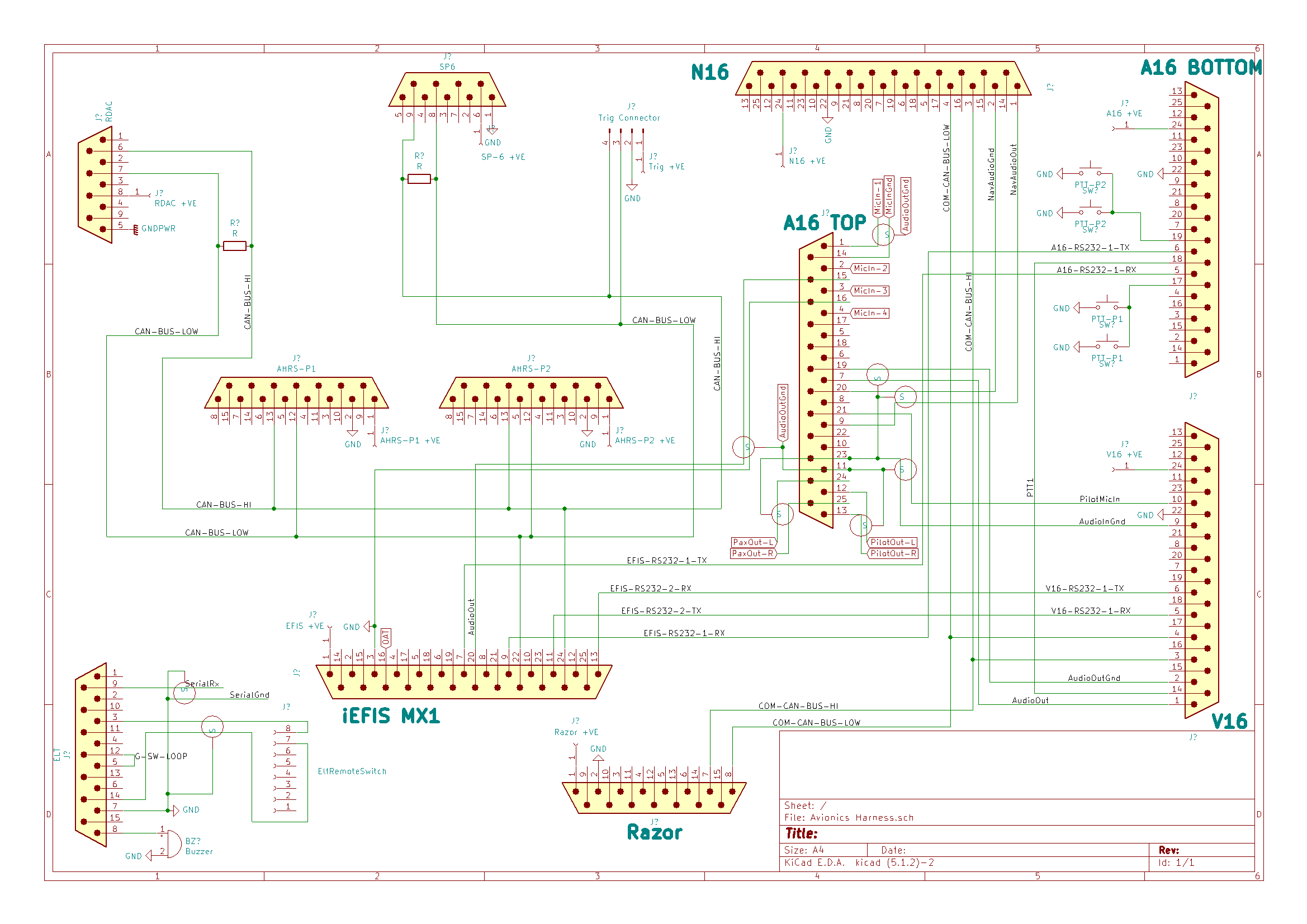
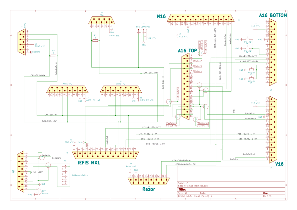
- Avionics all remote units on a rack in the back
- All fuses rather than breakers (reduced risk of failure at lower cost – what’s not to love?)
- Test circuit provides test of annunciator lamps (idiot lights) and fuses during pre-flight
- PIDG connectors everywhere in the power haress and crimped pins in the DB25 connectors to the electronic systems
- Grounding using a “forest of grounds” on both sides of the firewall. Only the wing and tail nav lights are grounded through the body, everything else uses a ground wire back to the firewall.
Learning a CAD package is non-trivial. I have spent many hours in Solidworks and on occasion thought to myself, “this is a waste of time, I should be working!” However, I have now found 4 separate errors in the panel that would have resulted in having to recut it. Given I have to get 6061-T6 from spruce in the USA, shipped by UPS, it comes out to about $150 per 2’x’4 sheet delivered. Then the cutting it out labour on top of that means remaking it would not be cheap!
Solidworks is very expensive – I just bought it for work and a single seat in the UK is GBP4K + support! Joining EAA gets you a student engineer license as part of your membership. I recommend it!
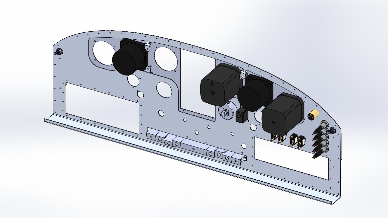
As I can’t get to the aircraft at the moment due to the Covid-19 lockdown, I decided to “waste” some time tracking down 3D models of instruments to stick into this model. It turned out not to be a waste of time at all. I had left plenty of space for each instrument based on the hole patterns until I tried “installing” them in Solidworks and they snagged on the shock mounts and the edge of the cut-out for the subassembly.
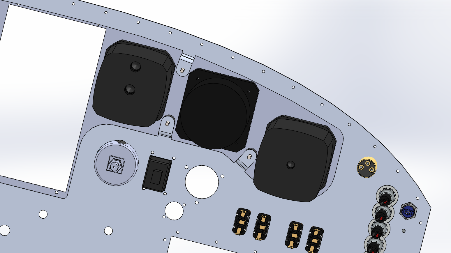
I didn’t have a model for the MGL Blaze unit I’m using as DI and AHRS so was going to assume it must be the same as the other instruments – they’re all standard, right? Wrong. I knocked up the Blaze part and installed it in the subassembly which required more tweaking to get everything clear of snags and obstructions.
In short – all the time spent in CAD has saved money, aggrevation and the delay that would have occurred if I had to buy more Al in from the US.
The work has continued and progress has been made. (We’ve had an election so the passive voice seems to be in fashion.) This is the results of moving the panel from 2D CAD (QCAD) into SolidWorks (thanks to the EAA for the low-cost licence).
Much more to come and as I’m in documentation mode, I’m planning to update this over the next few days!
I stopped logging as it was more and more tearing things out and work etc. has been crazy. Almost everything is out of the fuselage that’s coming out. The windscreen still needs to be popped out which will hopefully happen next weekend.
All wiring, control cables, pulleys, fairleads are out of the fuselage. There is still some cleaning to be done under the floor and the cabin interior needs sanding re-priming and painting. I’m not putting back a headliner so the frames will be exposed and need to be clean and smooth for painting. The rear of the baggage compartment will need a single piece cover which I intend to fabricate from .5mm(ish) Al sheet and cover.
Aft of that the consensus is don’t paint it, lather it in ACF-50, so 4 Litres of that is on order and the weed-killer sprayer has been “rescued” from the shed.
I have not got inside the wings yet; need to build a wing stand. Next week!
Micro-camera in the wing spar follow-throughs showed some surface corrosion. I’ve pulled one of the spar mounting blocks for a better look and it may be that it looked worse on the little camera than it is. I’m going to gently scotch-brite the interior of the box section to clean it out as much as possible and then stick the camera down again.
Lots of tidying up last weekend. Got shelves set up and all (most) aircraft parts off the floor.
Got the remainder of the fastenings out of the windshield bottom fairing. There is a wealth of silicone. I expect that despite the lack of bolts in accordance with the STC, this thing was going nowhere ever. It is bonded to the fuselage. It looks like it will require gentle heating around the periphery to get it out. To be continued.
The seats are uncovered and mostly disassembled. The bottom part of the P1 and P2 seats were soft, saggy and generally uncomfortable and the backs had top corners that moved slightly independently of the rest of the seat.
It turns out that when they were recovered in 1978 they went from round-backed to square-backed by means of plywood glue an aluminium sheet and some nails. The plan is to keep the covers if possible, clean, paint, and rebuild the seats.
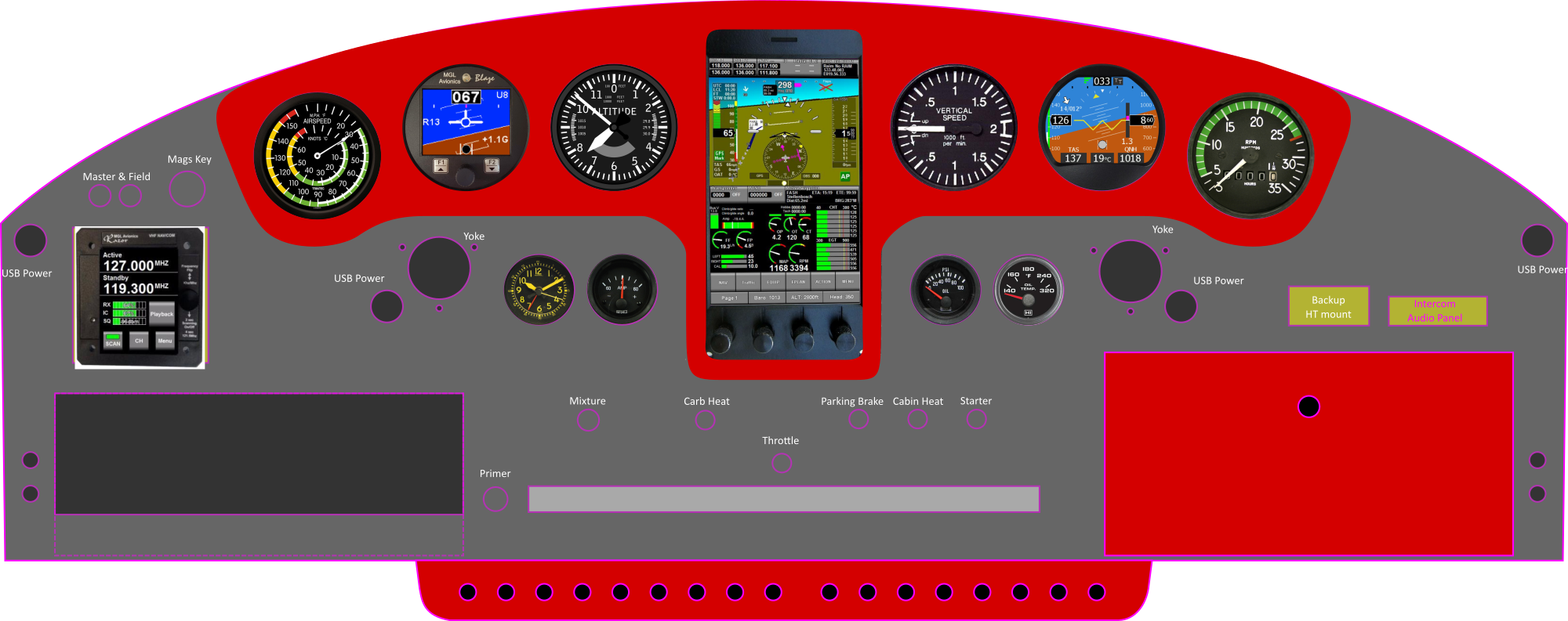
I’m attempting to strike a balance between keeping the quirky nature of a 170 panel and leveraging modern avionics – while NOT spending a fortune.
To that end, the venturis and gyros are gone and this is the draft of her new panel. I’m planning to print it at scae and stick it to the old panel and decide what I like/don’t.
Again the hours logged against this are a guesstimate over several days of on and off research and sketching.
Reading on the cessna170.org forum about someone’s missing windshield STC for the one-piece winshield in their plane I realized I didn’t see one in 80V’s docs either. Followed the discussion, posted a question and figured out that the windshield is not correctly installed. It appears to be a pre-drilled Great Lakes Aero windshield (https://www.youtube.com/watch?v=UjeLAgmA57A) that is not anchored to the airframe at the top.
Out she comes, which will give me access to the hand holds on the dash which need replacement and the front spare followthrough where the headliner was glued needs cleaning up as I’m not putting a headliner back in, so …
Never been happier to have chosen a “simple” aircraft. The electrical system is no more and I must submit plans for the new one to ILAS. To that end about 20 hours of work during the week, reading Bob Nuckolls (http://www.aeroelectric.com/) and drawing and redrawing circuit diagrams. I lost track so 20 is a minimum estimate … must do better logging.
More physical work resuming!