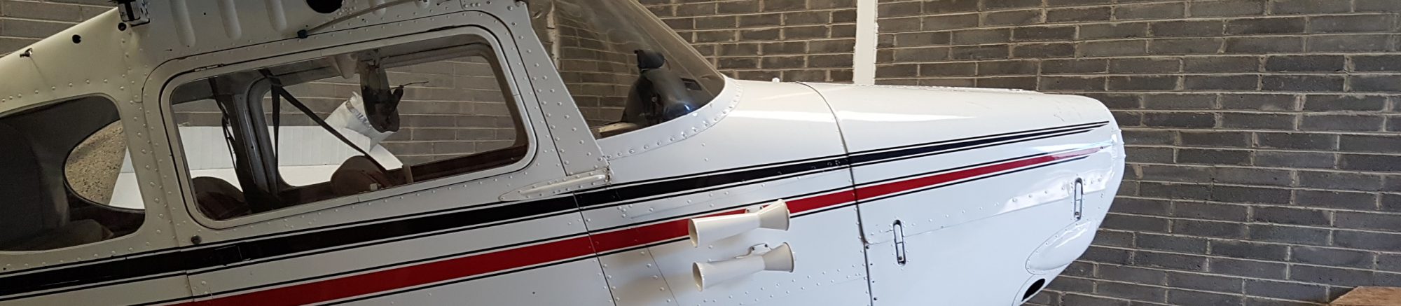
While discussing the conversion of the Thatcher CX5 to a tailwheel design it struck me that I have access to the C170 while its tail is off. It has survived 8 years as a school plane in the late 1940s early ’50s. 70 years and 4000+ landings later she is still in one piece, albeit with a repair doubler or two! May not be directly relevant to the CX5, but should add to the general fund of knowledge. Here’s what I measured:
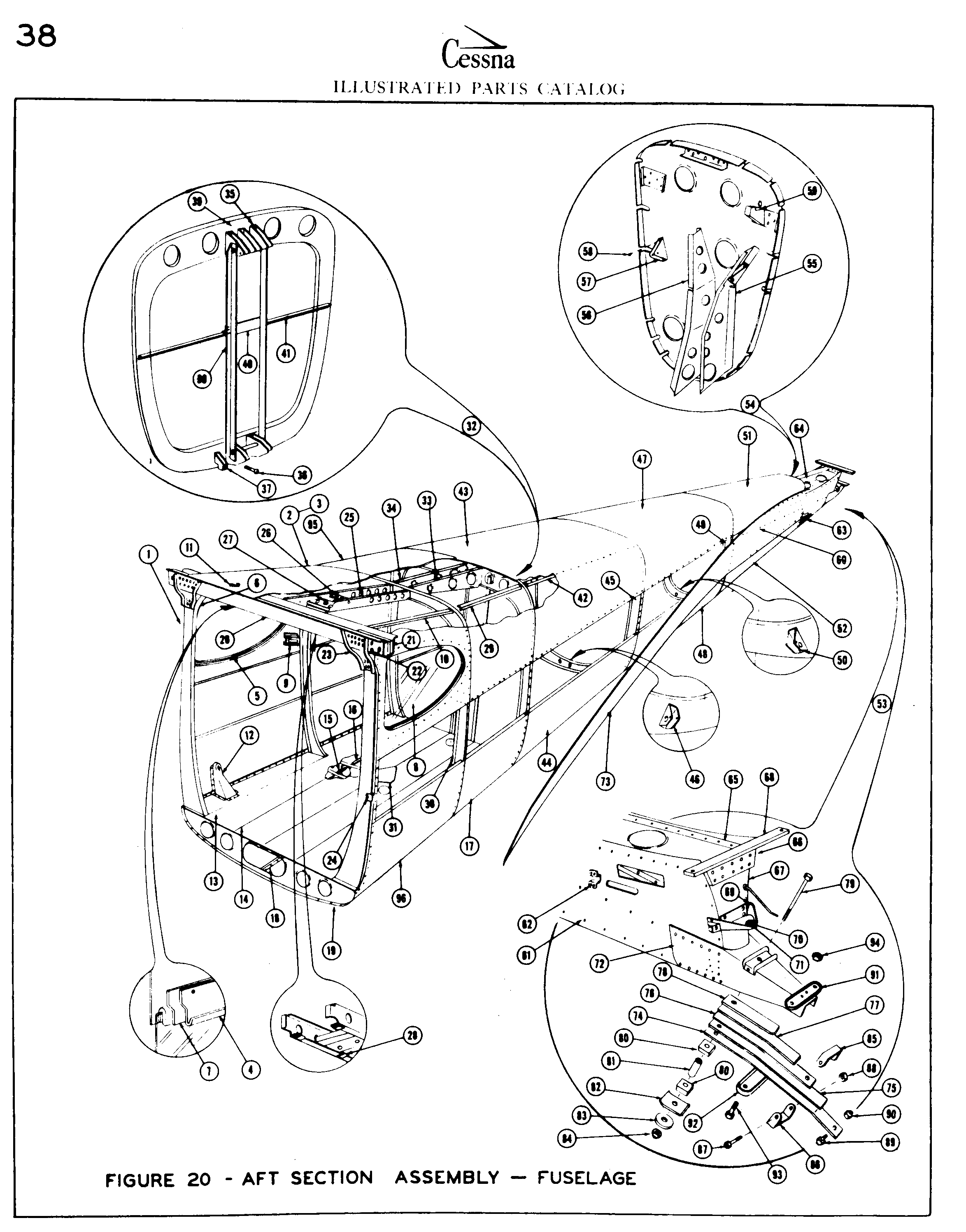
The parts catalog was hand drawn in 1948, and this is a print of a scan so not always the clearest. The parts have part numbers in the reference tables, but no thicknesses. The values here are hand measured from the airframe.
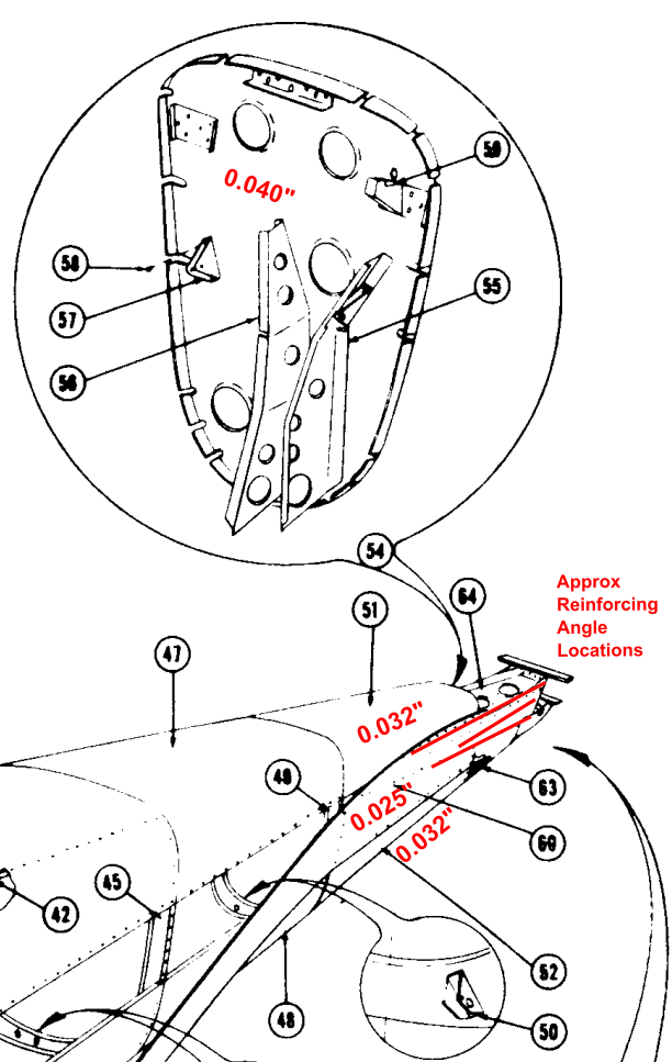
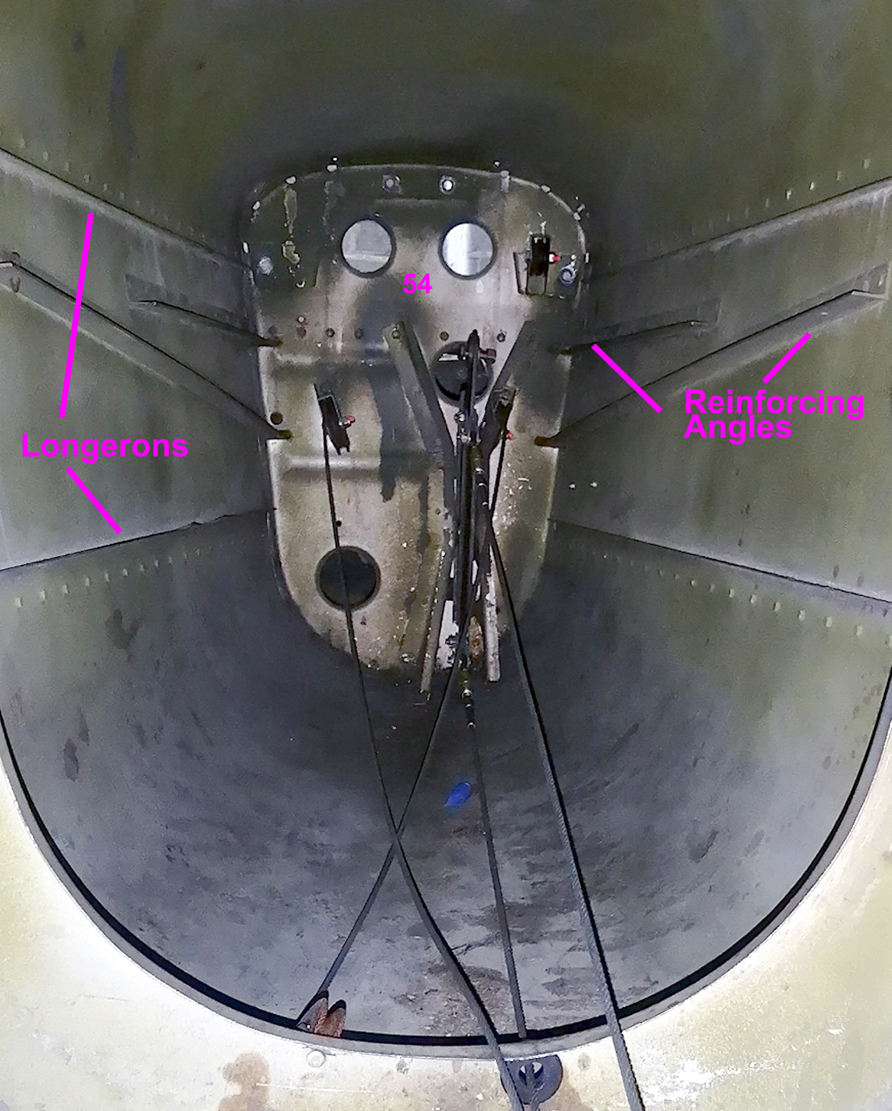
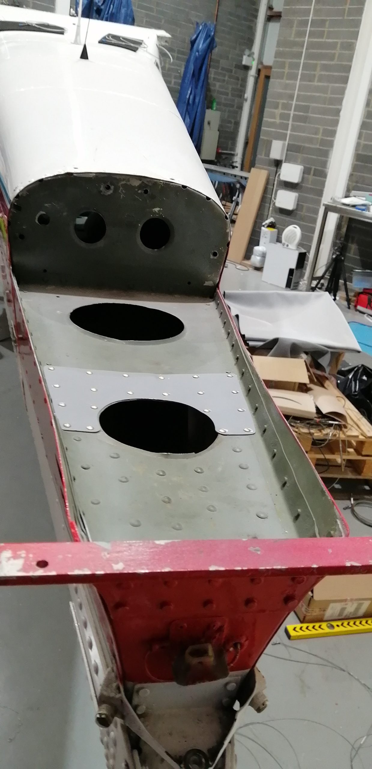
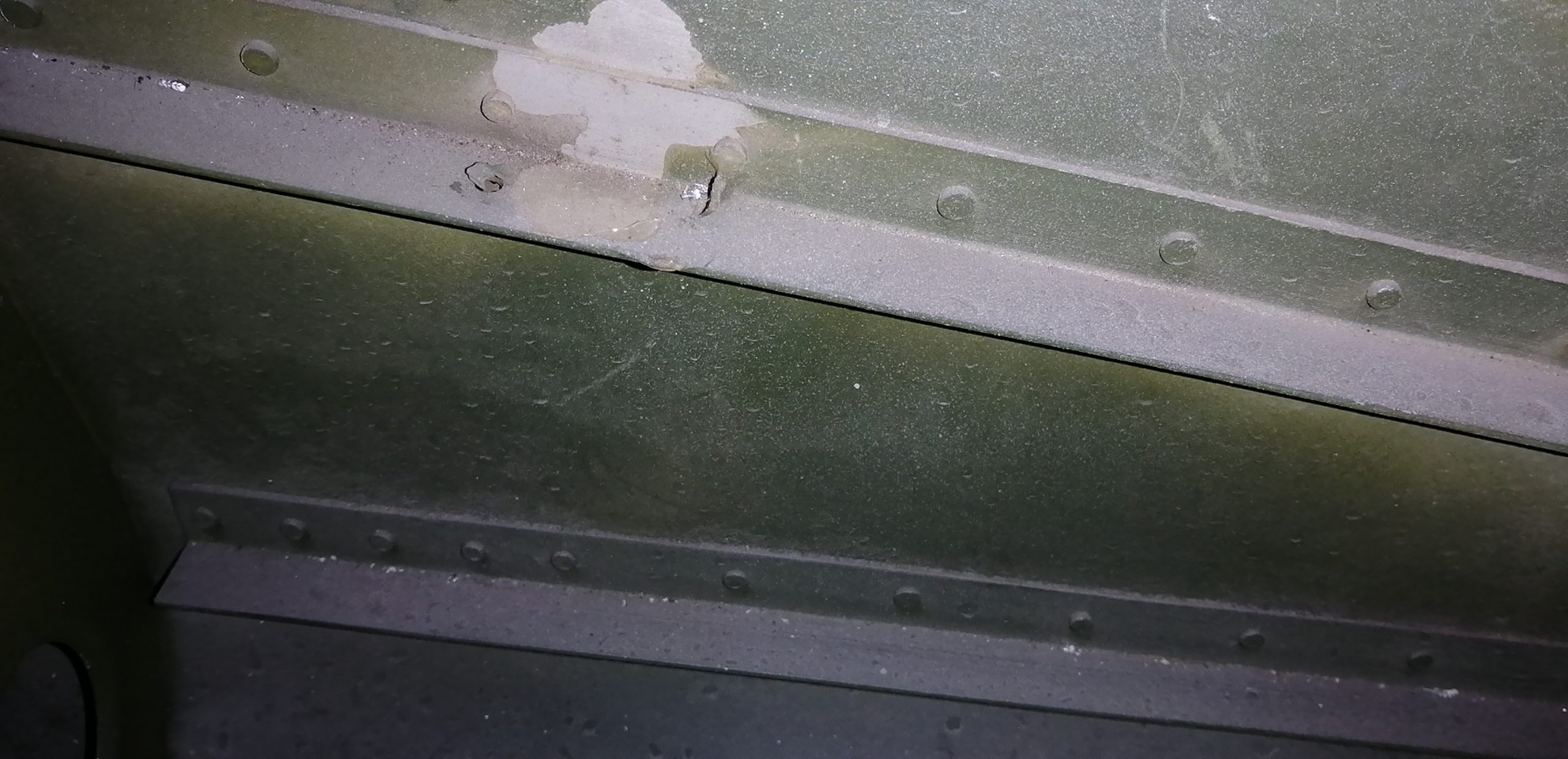
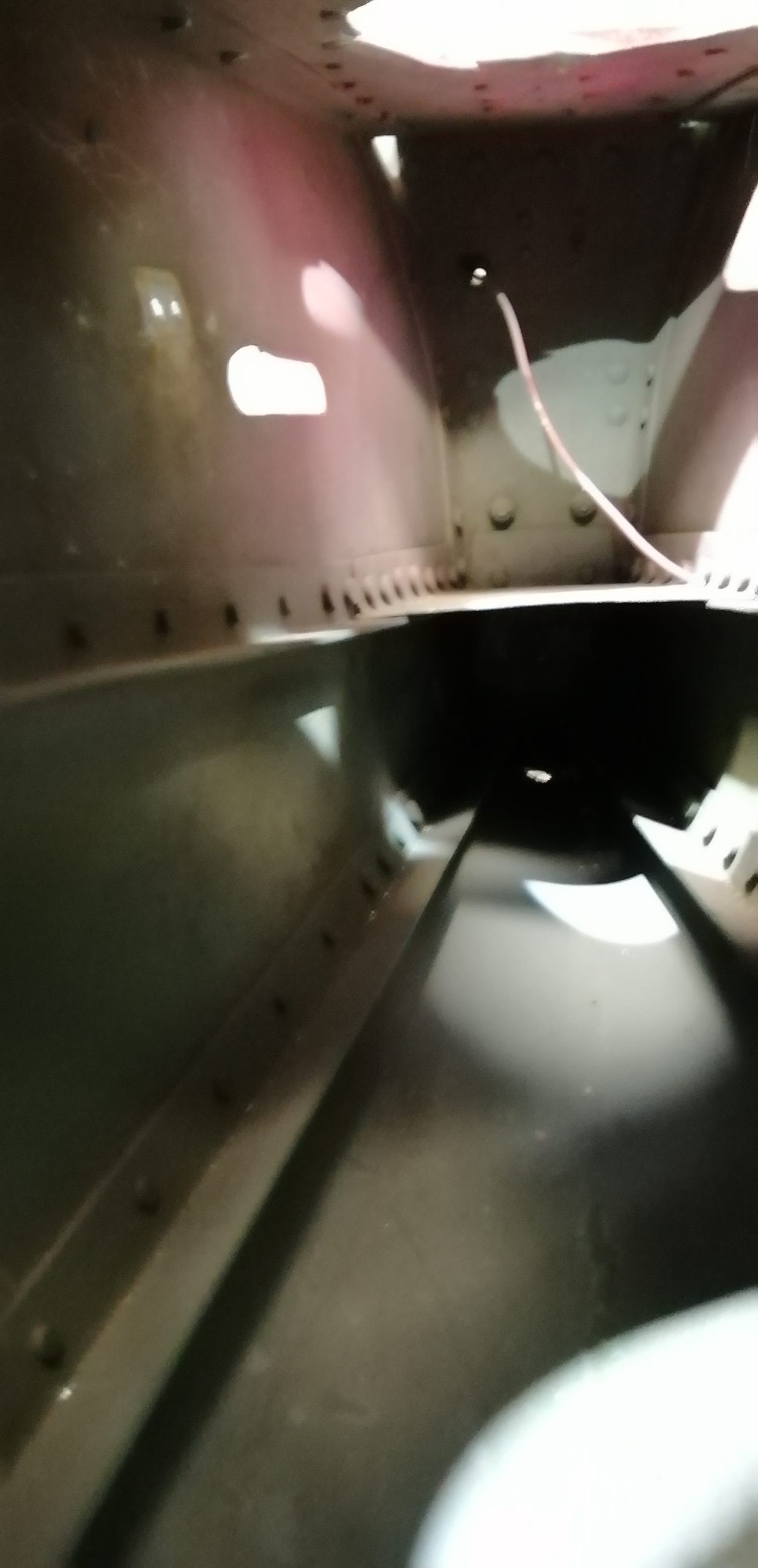
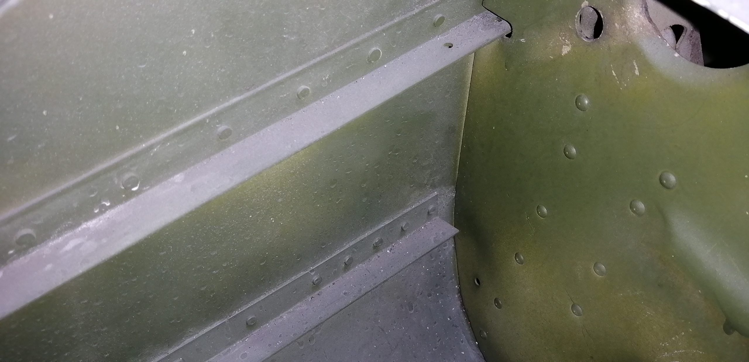
The locations of the reinforcing angles is approximate on the drawing and are better seen in the photo below. While the “splice skin” seemed to be .025″, I would be inclined to push it to .032″ as thats where the reinforcing angles attach.
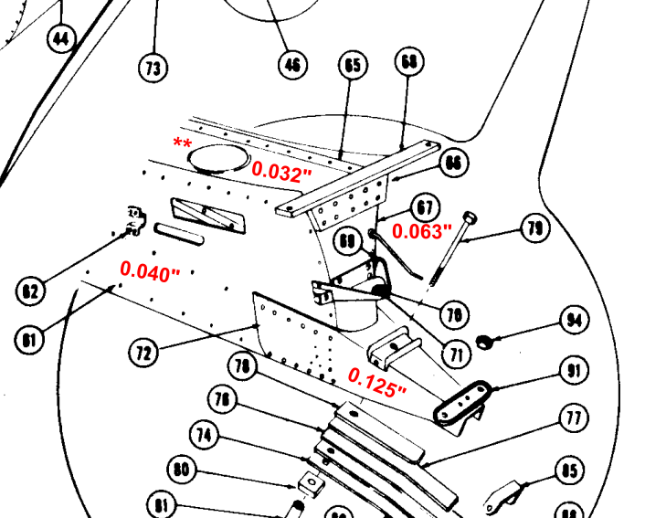
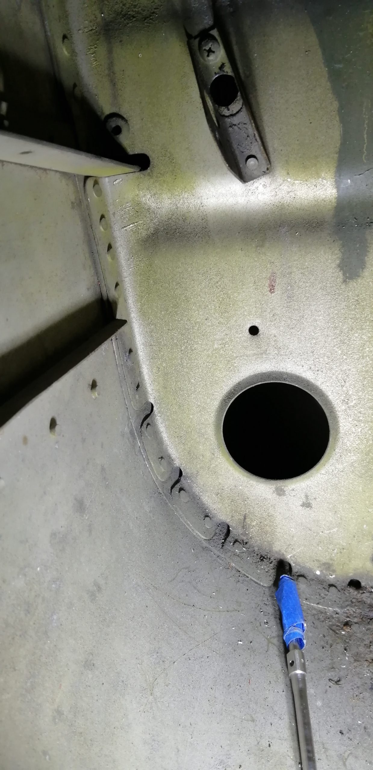
** While the horizontal bulkhead is measured at .032″, it has cracked and had .040″ doublers installed, so might be worth increasing this thickness.
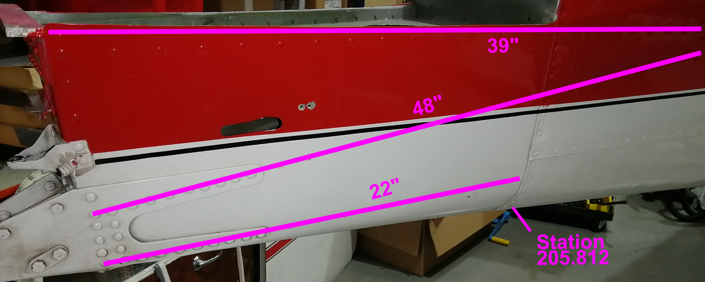
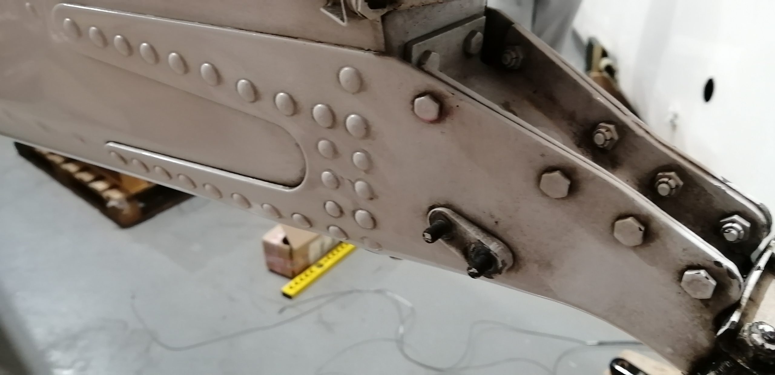
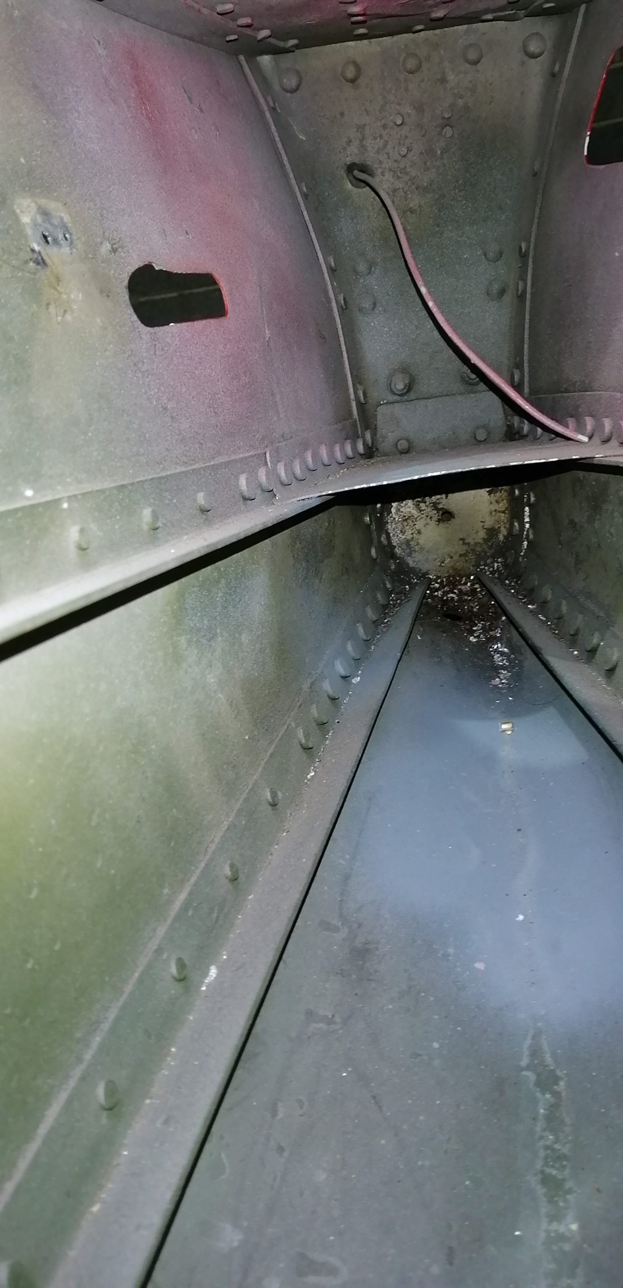
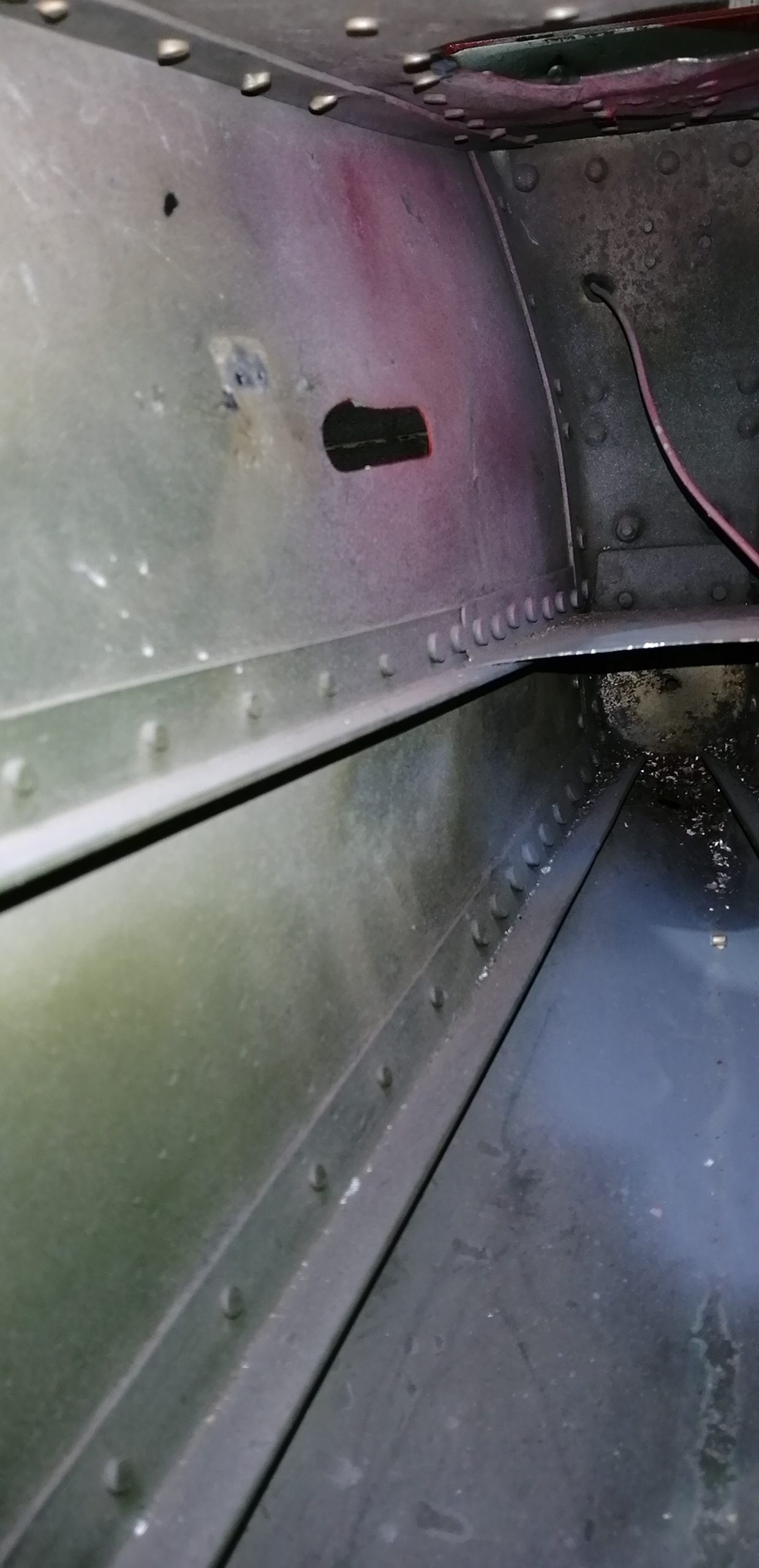
These are approx 3/4″ x 3/4″ x 1/8″ angles. The longer ones go through slots in the bulkhead at station 205.812 (inches from the firewall).
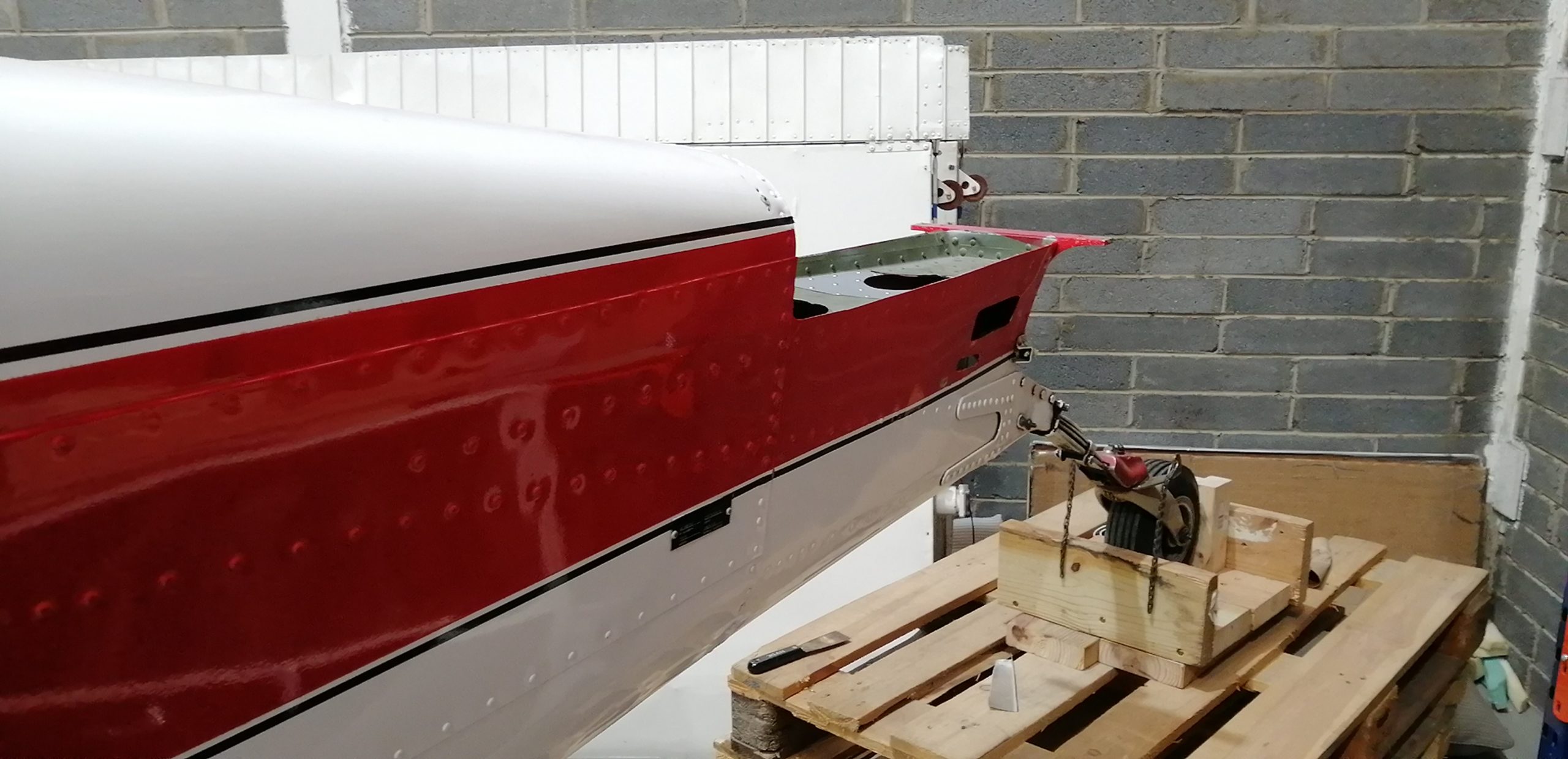
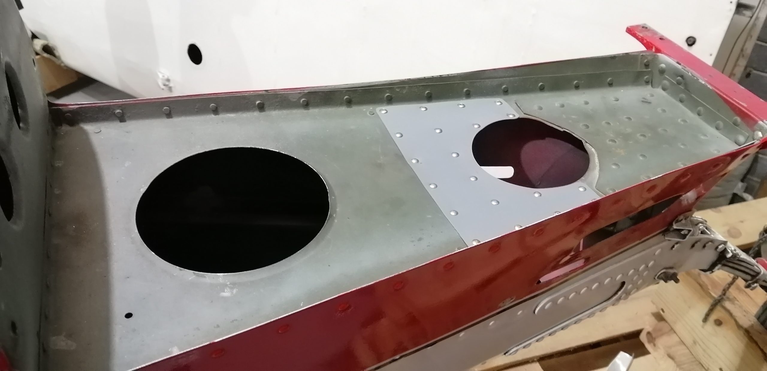
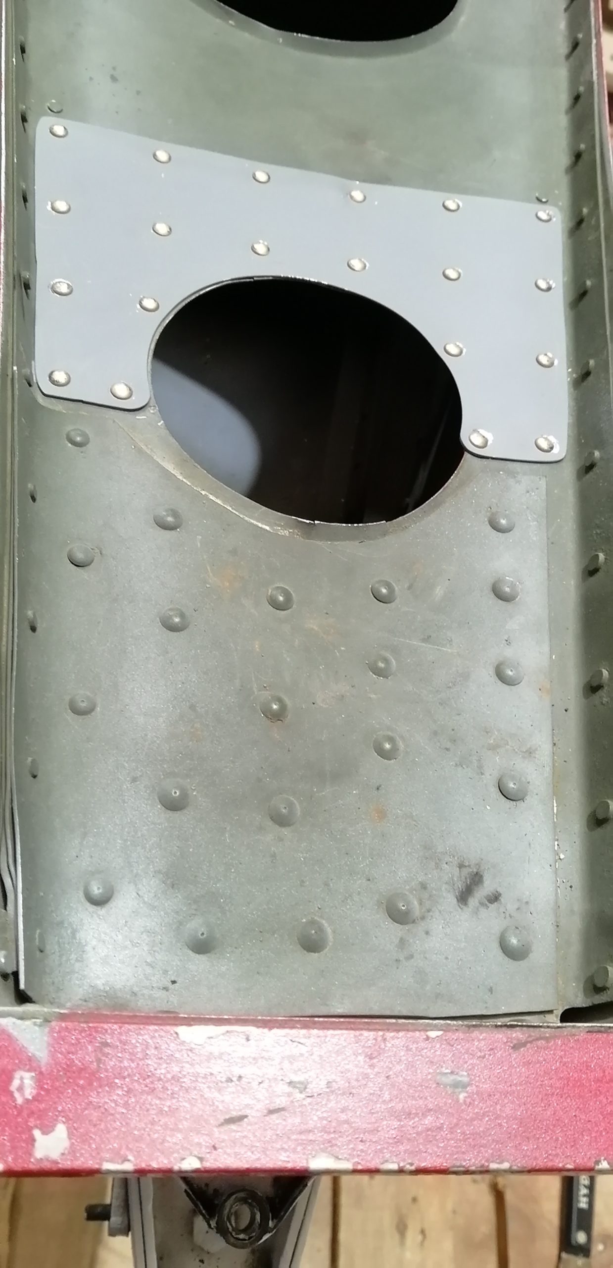
Above is the outside view showing the rivets into the reinforcing angles, below is the inside view of the same.
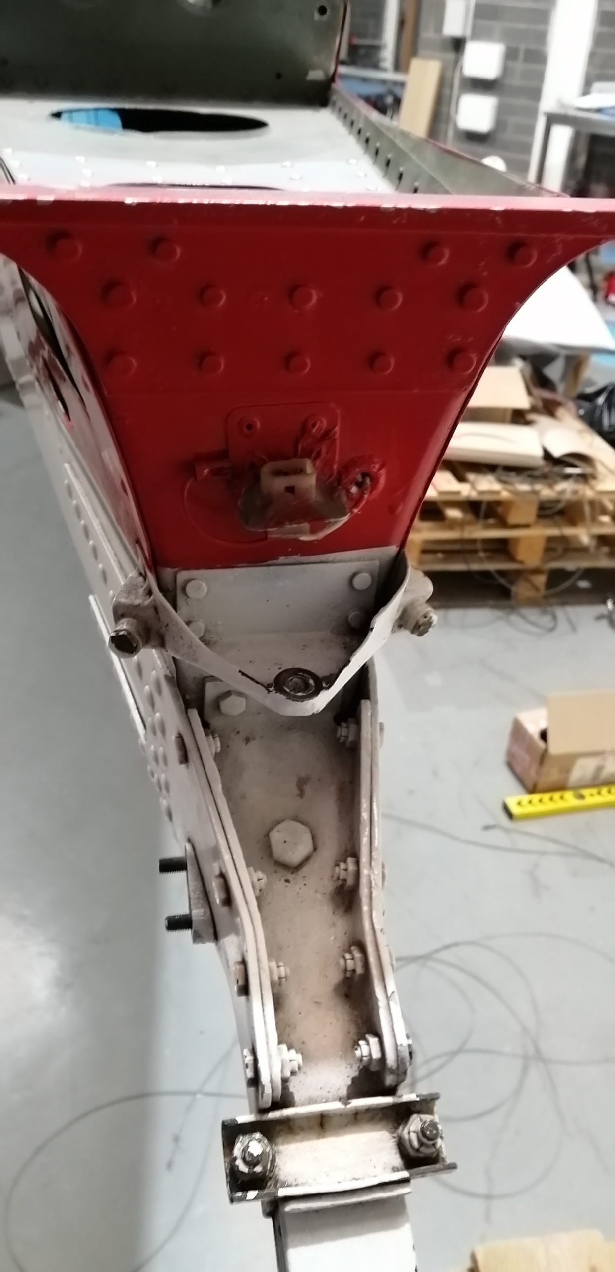
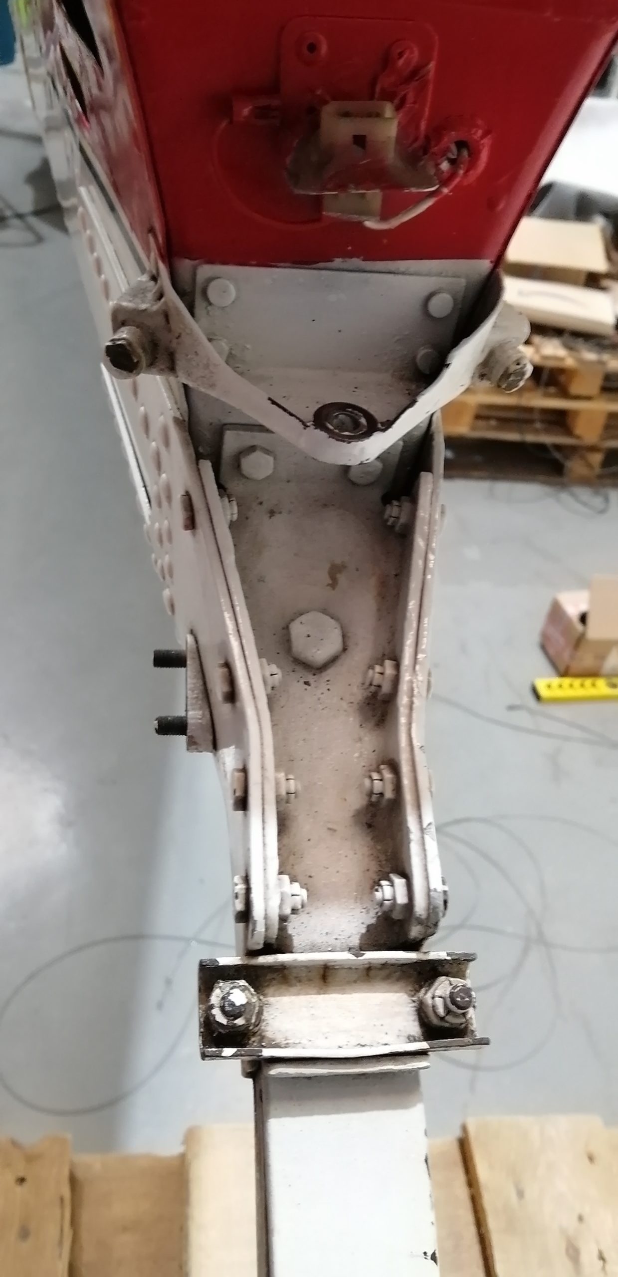
Hopefully this is of use. If nothing else I have a much better feel for how the tailwheel stresses are transmitted to the fuselage, so a useful exercise.